
Coil component
a technology of components and coils, applied in the field of coil components, can solve problems such as inability to achieve stable coupling coefficients, achieve the effects of reducing heat capacity differences, facilitating the formation of solder fillets, and enhancing mounting strength and connection reliability
- Summary
- Abstract
- Description
- Claims
- Application Information
AI Technical Summary
Benefits of technology
Problems solved by technology
Method used
Image

Examples
first embodiment
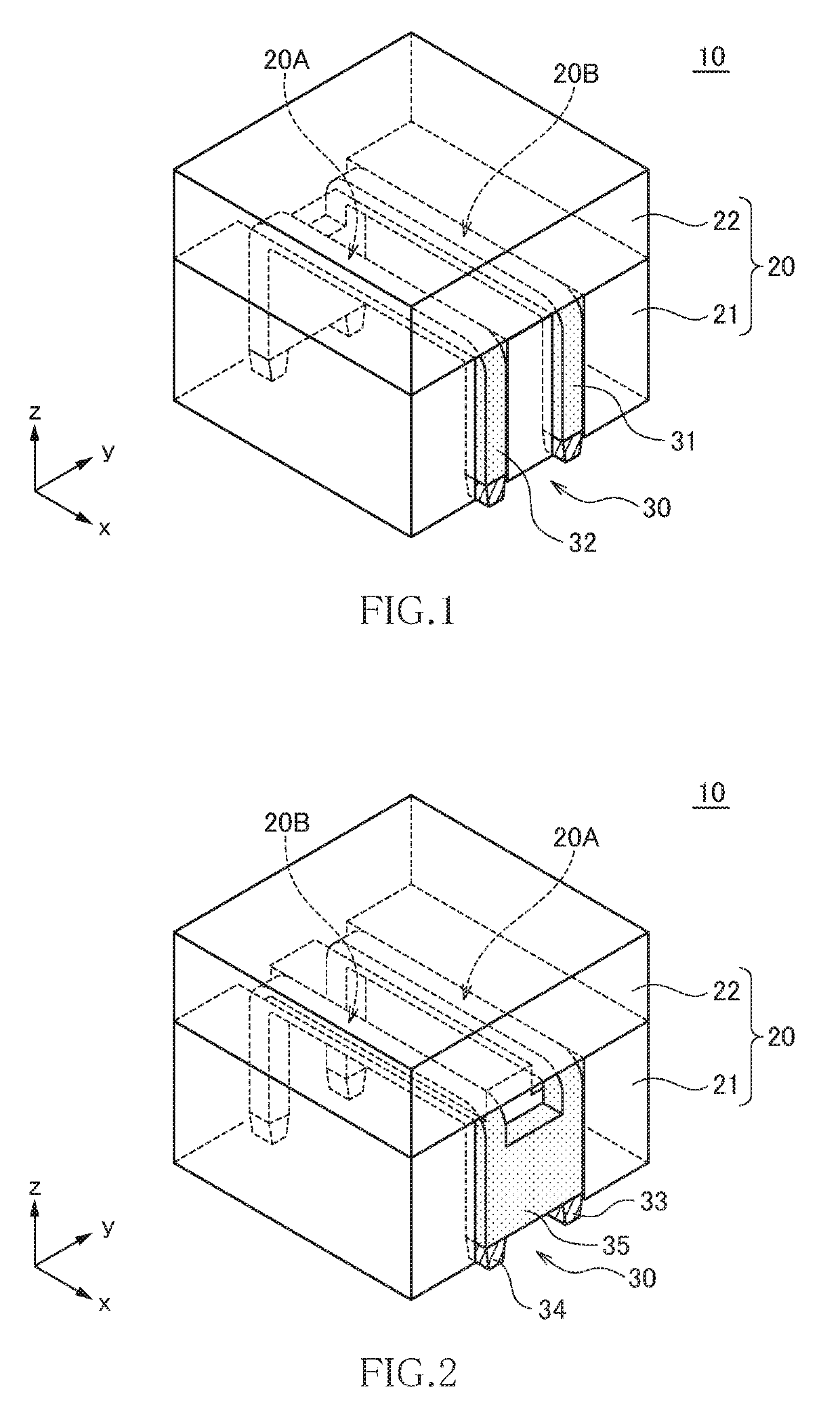
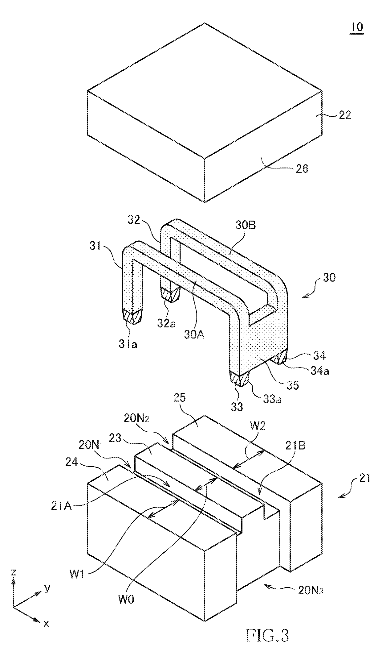
[0034]FIGS. 1 and 2 are perspective views for explaining the outer appearance of a coil component 10 according to the first embodiment of the present invention, which illustrate the structure as viewed from the mutually opposite sides. FIG. 3 is an exploded perspective view for explaining the structure of the coil component 10.
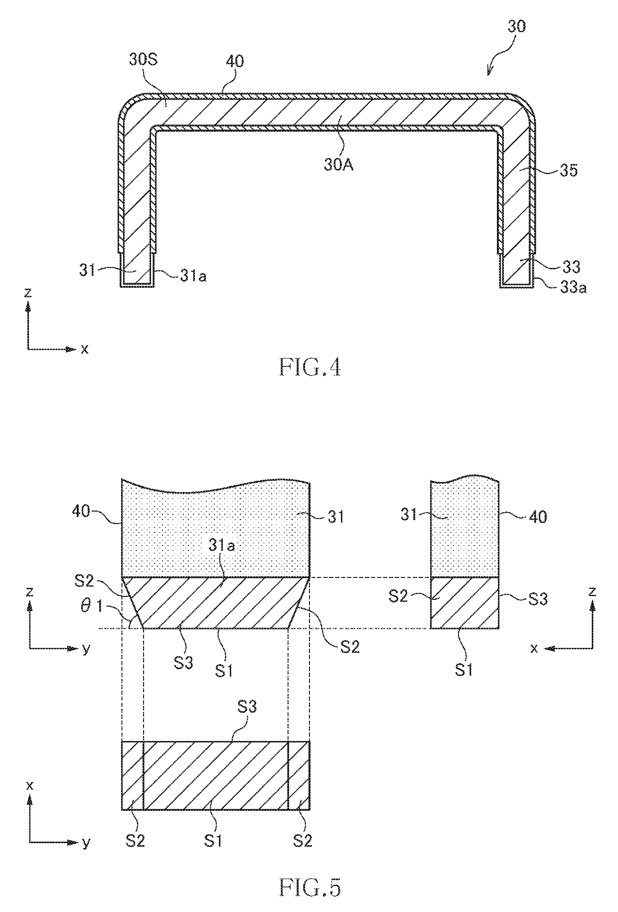
[0035]The coil component 10 according to the present embodiment is a coil component capable of being used as a coupled inductor and is constituted of a magnetic core 20 and a conductive plate 30, as illustrated in FIGS. 1 to 3. The magnetic core 20 includes a first core 21 positioned on the lower side in the z-direction and a second core 22 positioned on the upper side in the z-direction and has a configuration in which the first and second cores 21 and 22 are bonded to each other. While there is no particular restriction on the material of the magnetic core 20, NiZn-based ferrite, MnZn-based ferrite, a metallic magnetic member, and the like can be used. In ge...
second embodiment
[0071]FIG. 20 is a side view for explaining the structure of a coil component 60 according to the second embodiment of the present invention.
[0072]As illustrated in FIG. 20, the coil component 60 according to the second embodiment differs from the coil component 10 according to the first embodiment in that a first core 71 is used in place of the first core 21. Other configurations are the same as those of the coil component 10 according to the first embodiment, so the same reference numerals are given to the same elements, and overlapping description will be omitted.
[0073]The first core 71 used in the present embodiment differs from the first core 21 used in the first embodiment in that the first upper surface part 23 is lower in height than the second and third upper surface parts 24 and 25. With this configuration, the magnetic gap G formed in the middle leg part is selectively increased, so that the amount of the magnetic fluxes ϕA1 and ϕB1 that pass through the middle leg part r...
PUM
| Property | Measurement | Unit |
|---|---|---|
| thickness | aaaaa | aaaaa |
| thickness | aaaaa | aaaaa |
| thickness | aaaaa | aaaaa |
Abstract
Description
Claims
Application Information