Coil component

a technology of components and coils, applied in the field of coil components, can solve problems such as inability to achieve stable coupling coefficients, achieve the effects of reducing heat capacity differences, facilitating the formation of solder fillets, and enhancing mounting strength and connection reliability

Active Publication Date: 2022-06-07
TDK CORPARATION
View PDF12 Cites 0 Cited by
  • Summary
  • Abstract
  • Description
  • Claims
  • Application Information

AI Technical Summary

Benefits of technology

[0008]According to the present invention, the first and second body parts of the conductive plate are inserted respectively through the first and second through holes, thereby allowing the distance between the first and second body parts to be fixed. In addition, the area of the first and second outer leg parts is larger than that of the middle leg part, so that the magnetic flux components cancelling out each other prevails the magnetic flux components strengthening each other, with the result that a negative coupling coefficient required for a coupled inductor can be obtained.
[0018]As described above, the coil component according to the present invention can stably obtain a desired coupling coefficient having a negative value and can thus be suitably used as a coupled inductor.

Problems solved by technology

However, in the coupled inductor described in JP 2009-117676 A, two conductive plates are inserted through one through hole, so that the distance between the conductive plates is not fixed, resulting in an unstable coupling coefficient.
However, when the coil component described in Japanese Patent No. 2,951,324 is used as the coupled inductor, the following problem arises.

Method used


Image

  • Coil component
  • Coil component
  • Coil component

Examples


first embodiment

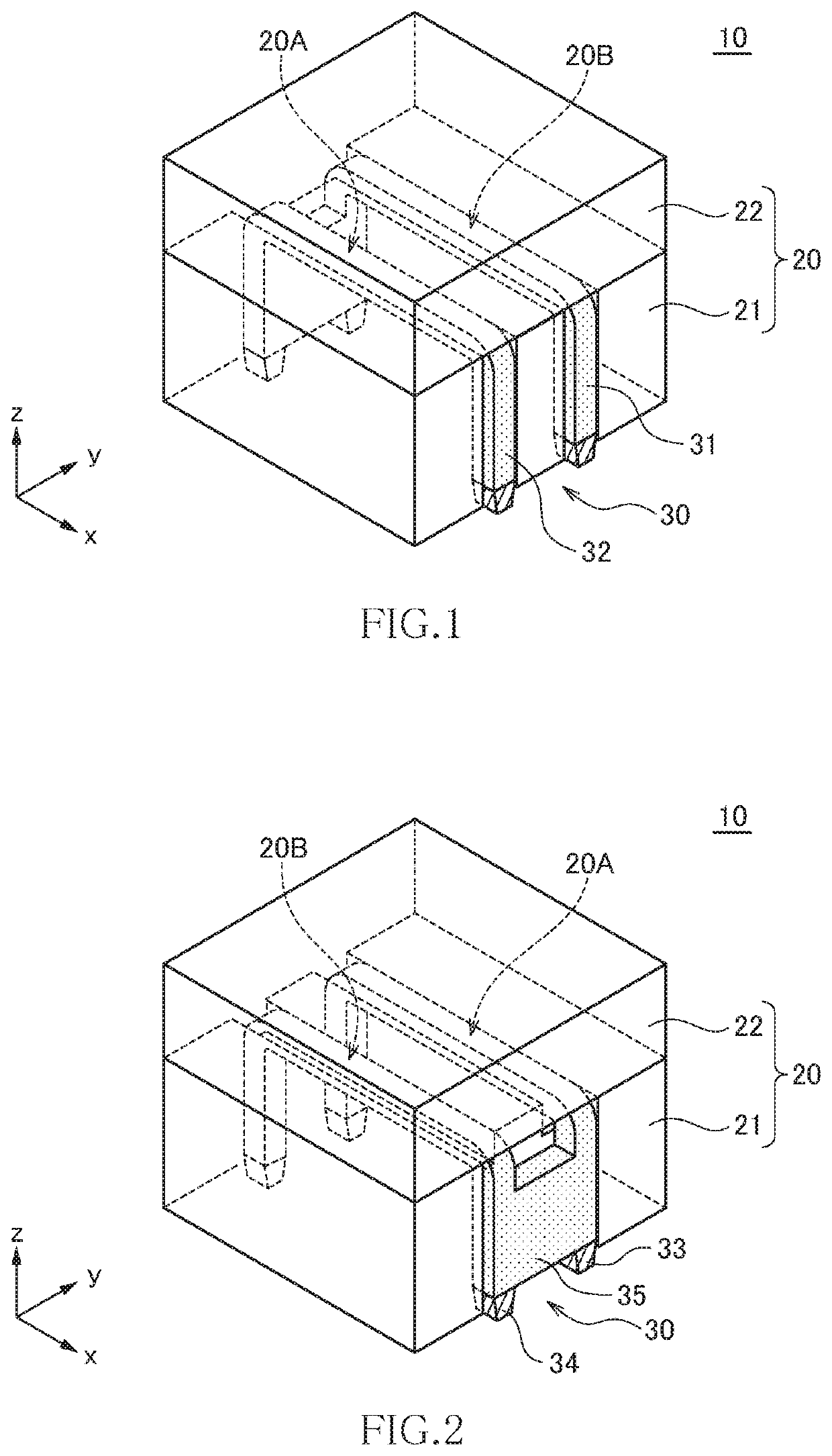
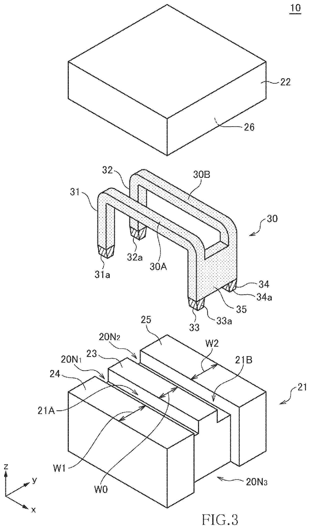
[0034]FIGS. 1 and 2 are perspective views for explaining the outer appearance of a coil component 10 according to the first embodiment of the present invention, which illustrate the structure as viewed from the mutually opposite sides. FIG. 3 is an exploded perspective view for explaining the structure of the coil component 10.

[0035]The coil component 10 according to the present embodiment is a coil component capable of being used as a coupled inductor and is constituted of a magnetic core 20 and a conductive plate 30, as illustrated in FIGS. 1 to 3. The magnetic core 20 includes a first core 21 positioned on the lower side in the z-direction and a second core 22 positioned on the upper side in the z-direction and has a configuration in which the first and second cores 21 and 22 are bonded to each other. While there is no particular restriction on the material of the magnetic core 20, NiZn-based ferrite, MnZn-based ferrite, a metallic magnetic member, and the like can be used. In ge...

second embodiment

[0071]FIG. 20 is a side view for explaining the structure of a coil component 60 according to the second embodiment of the present invention.

[0072]As illustrated in FIG. 20, the coil component 60 according to the second embodiment differs from the coil component 10 according to the first embodiment in that a first core 71 is used in place of the first core 21. Other configurations are the same as those of the coil component 10 according to the first embodiment, so the same reference numerals are given to the same elements, and overlapping description will be omitted.

[0073]The first core 71 used in the present embodiment differs from the first core 21 used in the first embodiment in that the first upper surface part 23 is lower in height than the second and third upper surface parts 24 and 25. With this configuration, the magnetic gap G formed in the middle leg part is selectively increased, so that the amount of the magnetic fluxes ϕA1 and ϕB1 that pass through the middle leg part r...


PUM

PropertyMeasurementUnit
thicknessaaaaaaaaaa
thicknessaaaaaaaaaa
thicknessaaaaaaaaaa

Abstract

Disclosed herein is a coil component that includes a magnetic core having first and second through holes extending in a first direction and arranged in a second direction perpendicular to the first direction, and a conductive plate including first and second body parts inserted respectively through the first and second through holes. The magnetic core includes a middle leg part positioned between the first and second through holes, a first outer leg part positioned on an opposite side to the middle leg part across the first through hole, and a second outer leg part positioned on an opposite side to the middle leg part across the second through hole. Area of each of the first and second outer leg parts defined by the first and second directions is larger than that of the middle leg part.

Description

BACKGROUND OF THE INVENTIONField of the Invention[0001]The present invention relates to a coil component and, more particularly, to a coil component capable of being used as a coupled inductor.Description of Related Art[0002]A coil component called “coupled inductor” may be used as a smoothing coil for a switching power supply such as a DC / DC converter. The coupled inductor has a pair of current paths magnetically coupled to each other. When current is made to flow in one current path, current also flows in the other current path by electromotive force. Thus, when the coupled inductor is used as a smoothing coil for a switching power supply, the peak of inrush current can be reduced.[0003]For example, JP 2009-117676 A describes a coupled inductor having a configuration in which two conductive plates are inserted through a through hole formed in a magnetic core.[0004]However, in the coupled inductor described in JP 2009-117676 A, two conductive plates are inserted through one through...

Claims


Application Information

Patent Timeline
Patent Type & Authority Patents(United States)
IPC IPC(8): H01F27/28H01F27/26H01F41/02H01F27/29
CPCH01F27/26H01F27/29H01F41/0206H01F17/04H01F27/38H01F27/306H01F27/292H01F3/14H01F27/2847H01F27/2852
Inventor ASHIZAWA, SYUNTOMONARI, TOSHIOOTSUKA, MASATO
Owner TDK CORPARATION
Why Eureka
Try Eureka