Orthopedic fixation system and method of use thereof

a fixation system and orthopedic technology, applied in the direction of internal osteosynthesis, surgical staples, osteosynthesis devices, etc., can solve the problems of difficult to achieve precise desired orientation of bone, bones, or bone pieces, and achieve the effect of facilitating fusion

a fixation system and orthopedic technology, applied in the direction of internal osteosynthesis, surgical staples, osteosynthesis devices, etc., can solve the problems of difficult to achieve precise desired orientation of bone, bones, or bone pieces, and achieve the effect of facilitating fusion

US20200000464A1Active Publication Date: 2020-01-02DEPUY SYNTHES PROD INC

Image

  • Orthopedic fixation system and method of use thereof
  • Orthopedic fixation system and method of use thereof
  • Orthopedic fixation system and method of use thereof

Examples


Embodiment Construction

[0038]As required, detailed embodiments of the present invention are disclosed herein; however, it is to be understood that the disclosed embodiments are merely exemplary of the invention, which may be embodied in various forms. It is further to be understood that the figures are not necessarily to scale, and some features may be exaggerated to show details of particular components or steps.

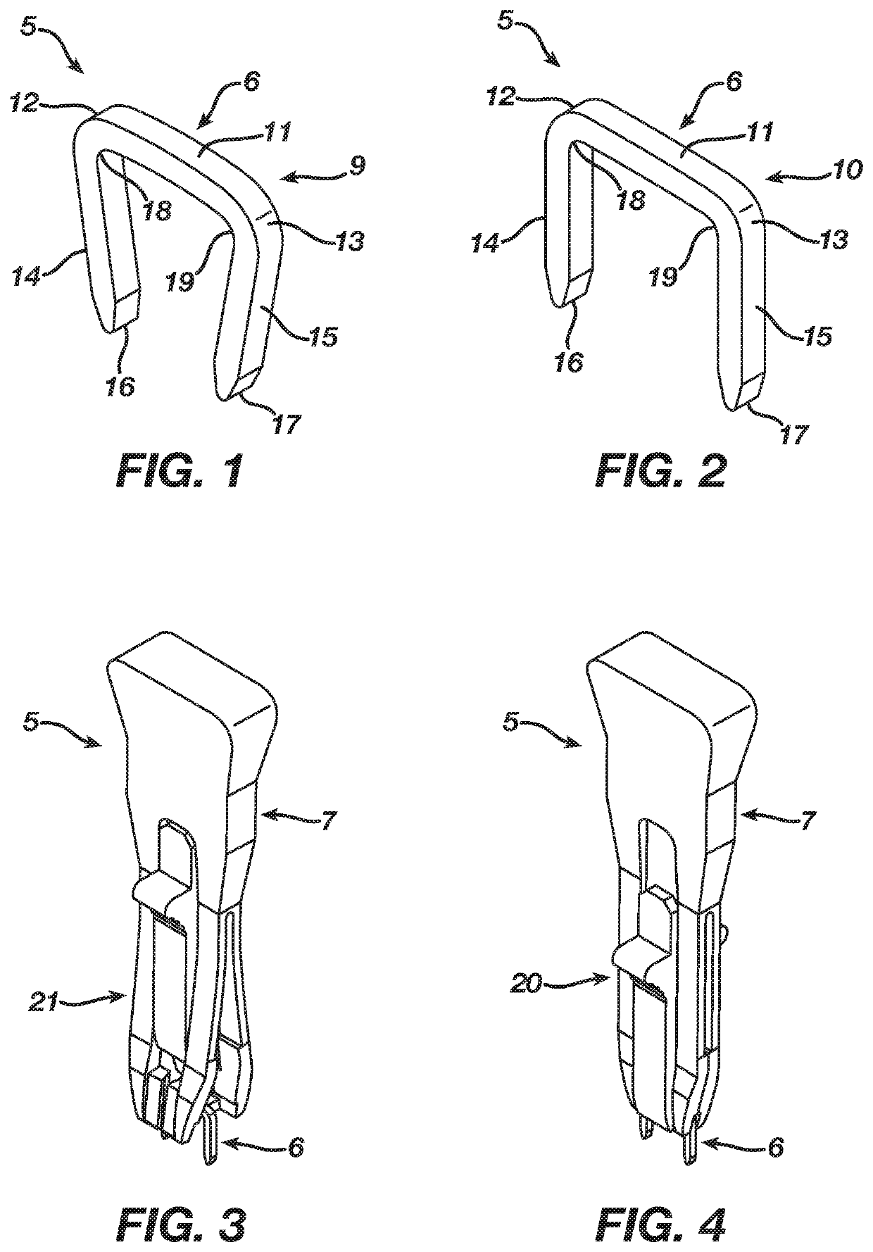
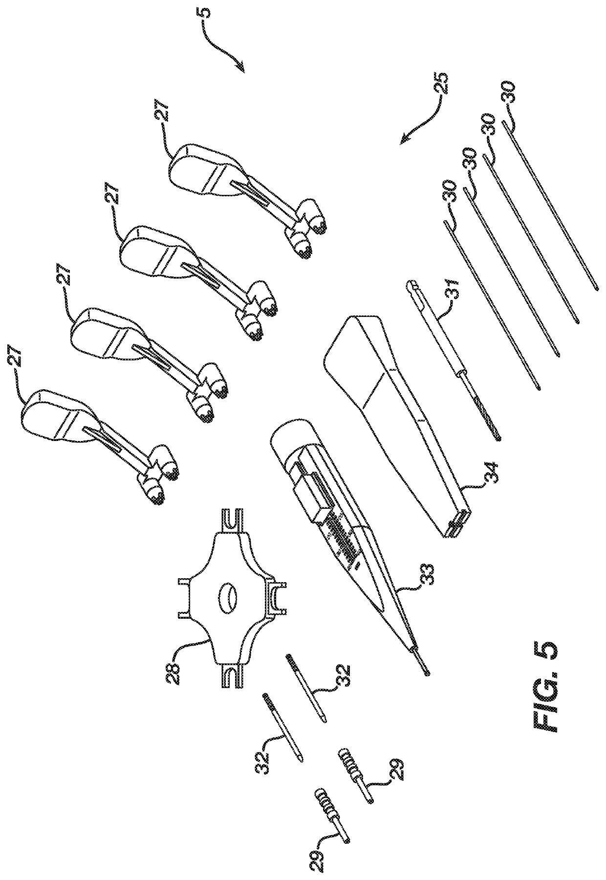
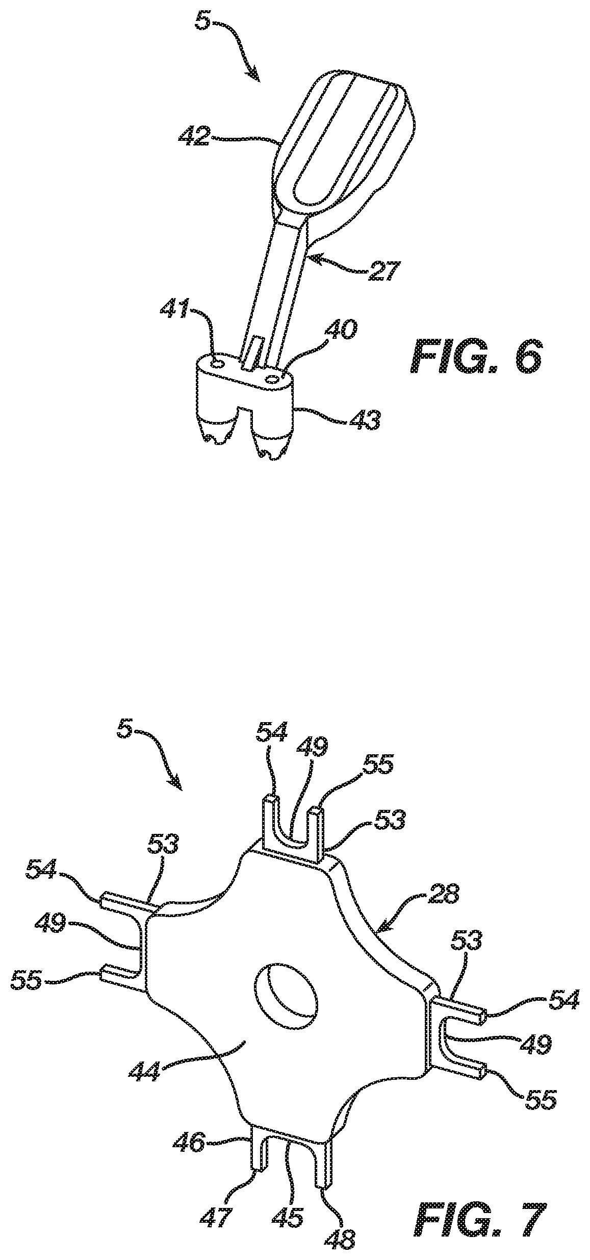
[0039]FIGS. 1-13 illustrate an orthopedic fixation system 5 according to a preferred embodiment of the present invention. Referring to FIGS. 1-4, the orthopedic fixation system 5 includes an implant 6 and a mechanical constraint, such as the implant insertion device 7, both of which are typically enclosed in a packaging. While the orthopedic fixation system 5 illustrated in FIGS. 1-4 show a single implant 6 and implant insertion device 7, one of ordinary skill in the art will recognize that the orthopedic fixation system 5 may include multiple implants 6 and implant insertion devices 7 packaged e...


PUM


Abstract

An orthopedic fixation system fuses bone, bones, or bone pieces in a predetermined anatomical position. The orthopedic fixation system includes an implant that transitions between an unconstrained shape and a constrained insertion shape, a drill guide, first and second K-wires, and a cannulated drill bit. The drill guide and the first and second K-wires retain the bone, bones, or bone pieces in an anatomical position corresponding with the predetermined anatomical position. The cannulated drill bit fits over the first and second K-wires and drills, respectively, first and second drilled holes into the bone, bones, or bone pieces. After insertion of the implant into the first and second drilled holes, the implant attempts to transition from its constrained insertion shape to its unconstrained shape such that the implant continuously compresses the bone, bones, or bone pieces thereby holding the bone, bones, or bone pieces in the predetermined anatomical position.

Description

BACKGROUND OF THE INVENTION1. Field of the Invention[0001]The present invention relates to orthopedic fixation of bone, bones, or bone pieces, and, more particularly, but not by way of limitation, to an orthopedic fixation system and a method of use thereof.2. Description of the Related Art[0002]Orthopedic fixation often involves implantation of an implant, such as an orthopedic staple, into bone, bones, or bone pieces. The implant, which typically is formed from a shape memory or superelastic material (e.g., Nitinol), includes a natural unconstrained shape and further deforms to store energy and transition to an insertion shape. The implant inserts into the bone, bones, or bone pieces in its insertion shape. Once implanted, the implant attempts to transition from its insertion shape to its unconstrained shape, thereby delivering its stored energy and creating a compression that assists in healing the bone, bones, or bone pieces.[0003]In order to insert an implant into bone, bones, ...

Claims


Application Information

Patent Timeline
02 Jan 2020
Publication
US20200000464A1
IPC
A61B17/064; A61B17/17; A61B17/10; A61B17/16
CPC
A61B2017/90; A61B2017/681; A61B17/0642; A61B2090/062; A61B17/1796; A61B17/10; A61B17/1637; A61B17/8897
Inventors
GASTON, GLENN; CHENEY, DANIEL F.