Camera system and camera fill light method

Active Publication Date: 2020-02-27
LATTICE ENERGY TECH CORP
View PDF8 Cites 1 Cited by
  • Summary
  • Abstract
  • Description
  • Claims
  • Application Information

AI Technical Summary

Benefits of technology

[0011]Through the above system and the fill light method, the dislocation result of the difference between the current position of the fill light and the optimal placement of the fill light is calculated, and a prompt message is generated according to the dislocation re

Problems solved by technology

The images may be affected by the brightness of the environment at the time it were taken, resulting that main features of the images (such as portraits, dishes, or artworks) were too dark and unappealing overall.
However, the entry level of this method is relative high, and the modified images will not felt authentic, for example the inconsistency in chroma and brightness of the adjacent areas in the image, or the inconsistency of the reflections (such as reflected light in the eyes).
For example, when the fill light is put t

Method used


Image

  • Camera system and camera fill light method
  • Camera system and camera fill light method
  • Camera system and camera fill light method

Examples


Embodiment Construction

[0019]To facilitate understanding of the object, characteristics and effects of this present disclosure, embodiments together with the attached drawings for the detailed description of the present disclosure are provided.

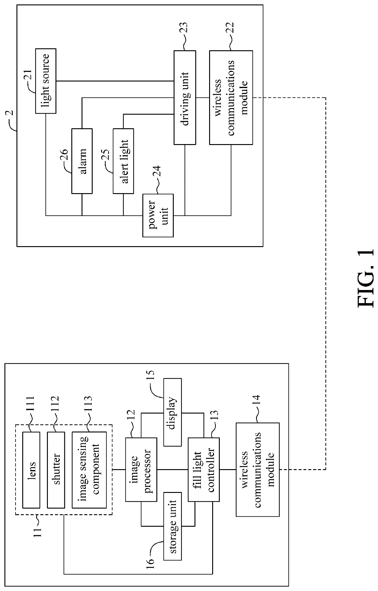
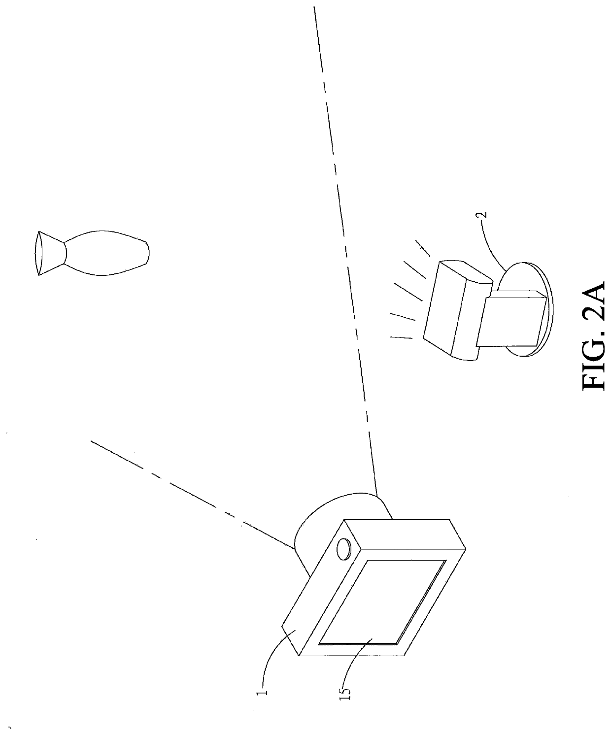
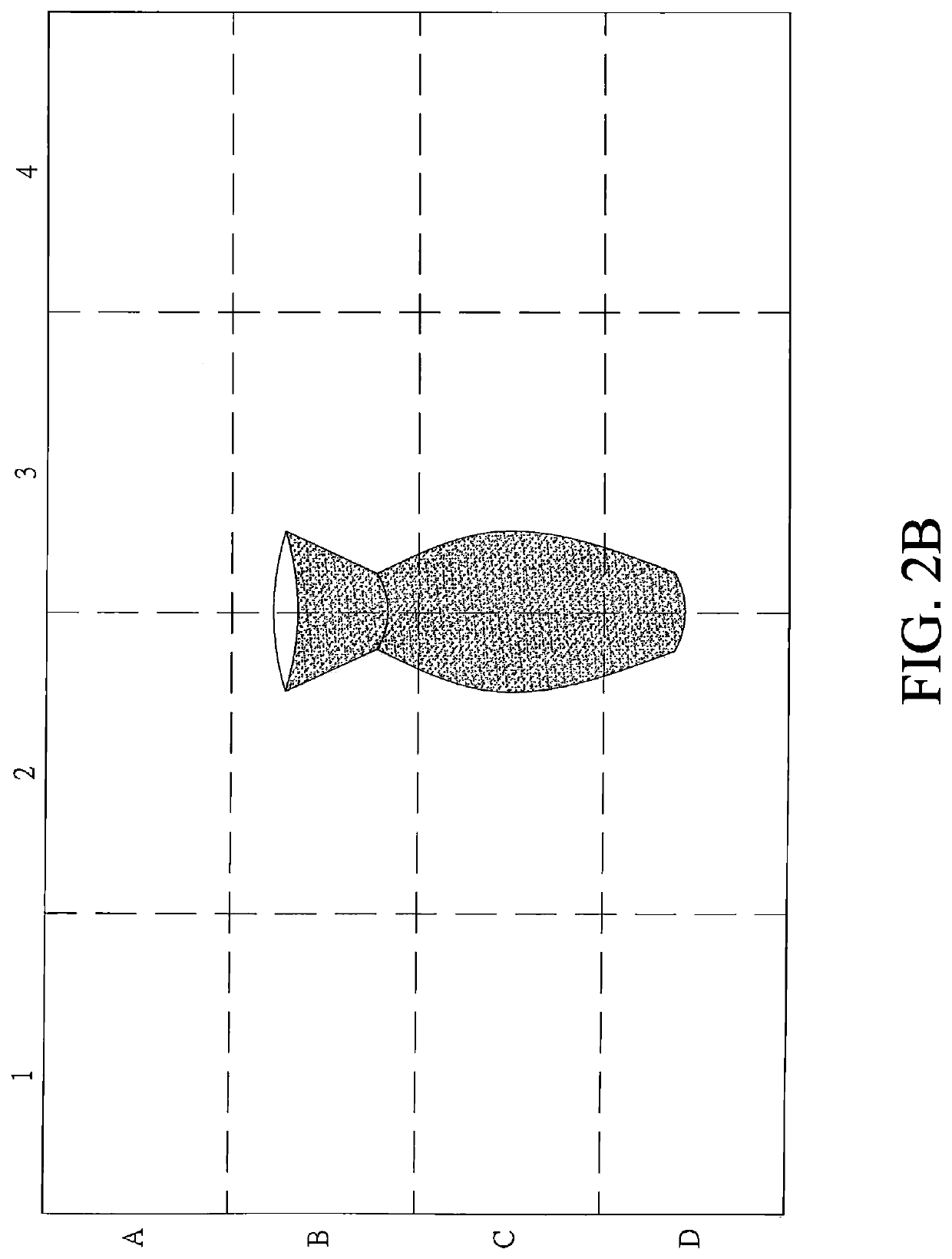
[0020]Please refer to FIG. 1, which is a block diagram of a camera system and a fill light according to the present invention. The present invention is mainly divided into two areas, a camera system 1 and a fill light 2, and the fill light 2 is an off-camera flash. The fill light 2 and the camera system 1 are separated from each other. The camera system 1 communicates with the fill light 2 through wireless communications connection. The camera system 1 and the fill light 2 perform a test shot first, and a result of dislocation is obtained through test shooting, and then perform an actual shooting to obtain an actual image information.

[0021]The camera system 1 includes a camera 11, an image processor 12, a fill light controller 13, a wireless communications module 14...


PUM


Abstract

The present application related to a camera system and a camera fill light method. The camera system establishes a wireless communications connection with a fill light, captures an original image by a camera in the camera system, and then transmits a first test light signal to the fill light such that a first flash is performed by the fill light. The camera captures a first light source image during the first flash period of the fill light. A fill light controller in the camera system compares differences of the brightness or the chroma of different image information and, after determining the present location of the fill light, calculates a dislocation result of the present location of the fill light and the best placement location of the fill light. The camera system yields the dislocation result to the photographer via a notification message.

Description

CROSS-REFERENCES TO RELATED APPLICATION[0001]The present application claims priority under 35 U.S.C. § 119(a) to U.S. provisional Patent Application No. 62 / 722,986, filed on Aug. 27, 2018, in the US Intellectual Property Office, which is incorporated herein by reference in its entirety.BACKGROUND OF THE INVENTION1. Field of the Invention[0002]The present disclosure relates to a camera system, and in particular to a camera system and a camera fill light method for calculating a best placement position of a fill light through a test and providing a prompt message to the photographer.2. Description of the Related Art[0003]In recent years, optical digital cameras have become popular along with cloud technology. Many photographers like to upload their photos to the Internet for sharing. The images may be affected by the brightness of the environment at the time it were taken, resulting that main features of the images (such as portraits, dishes, or artworks) were too dark and unappealing...

Claims


Application Information

Patent Timeline
IPC IPC(8): H04N5/235H04N17/00
CPCH04N17/002H04N5/2354H04N23/56H04N23/71H04N23/74
Inventor CHIEN, TA-YILAI, YING-JUCHEN, YUNG-CHOULIAO, WEI-HUNGHU, FEN-LING
Owner LATTICE ENERGY TECH CORP
Why Eureka
Try Eureka