Concrete screed power control linkage

Active Publication Date: 2020-03-05
CURB ROLLER
View PDF0 Cites 1 Cited by
  • Summary
  • Abstract
  • Description
  • Claims
  • Application Information

AI Technical Summary

Benefits of technology

[0010]A first aspect of the present invention concerns a power unit for a concrete screed, wherein the screed includes a rotatable concrete forming drum and is configured to be manually advanced in a forward direction. The power unit broadly includes a frame, a powered drive, and a mechanical control connection. The frame includes a drive housing and a handle to be grasped by a user, with the handle being configured to facilitate manual advancement of the concrete screed in the forward direction. The handle includes a grip and a relatively shiftable user-operated drive controller. The powered drive is operably supported by the drive housing and includes an electric motor and a drive shaft powered by the motor to rotate the drum. The powered drive further includes a shiftable drive control element operable to control the electric motor and thereby rotation of the drum. The mechanical control connection extends between the drive controller and the drive control element so that shifting of the drive controller corresponds with shifting of the drive control element.
[0011]A second aspect of the present invention concerns a power unit for a concrete screed, wherein the screed include

Problems solved by technology

However, prior art concrete forming tools have certain deficiencies.
As such, powered concrete forming tools are well known as being bulky and heavy, such that the tool is difficult to transport and operate in a precise manner.
For instance, powered screeds generally require more than one operator to advance the screed an

Method used


Image

  • Concrete screed power control linkage
  • Concrete screed power control linkage
  • Concrete screed power control linkage

Examples


Embodiment Construction

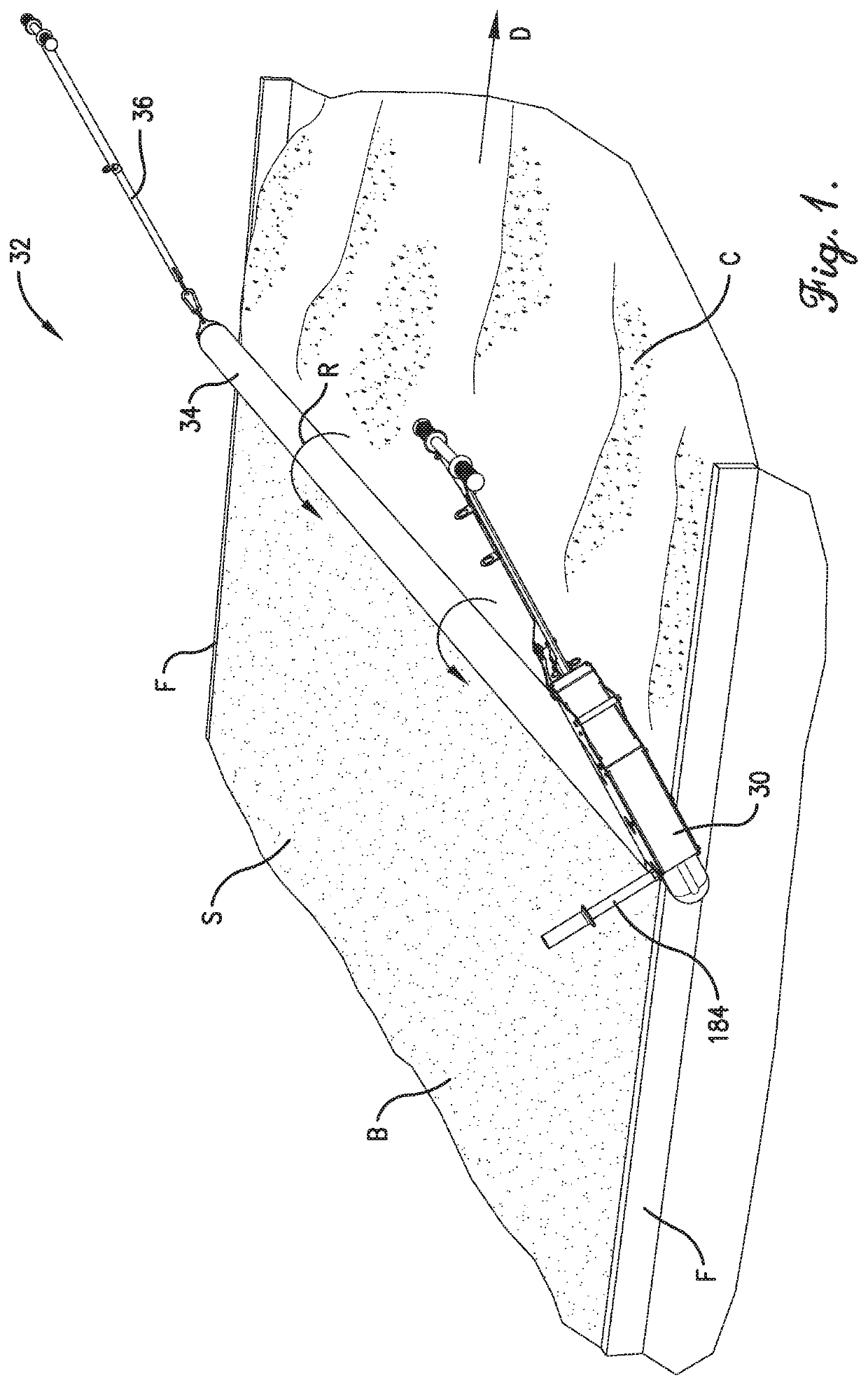
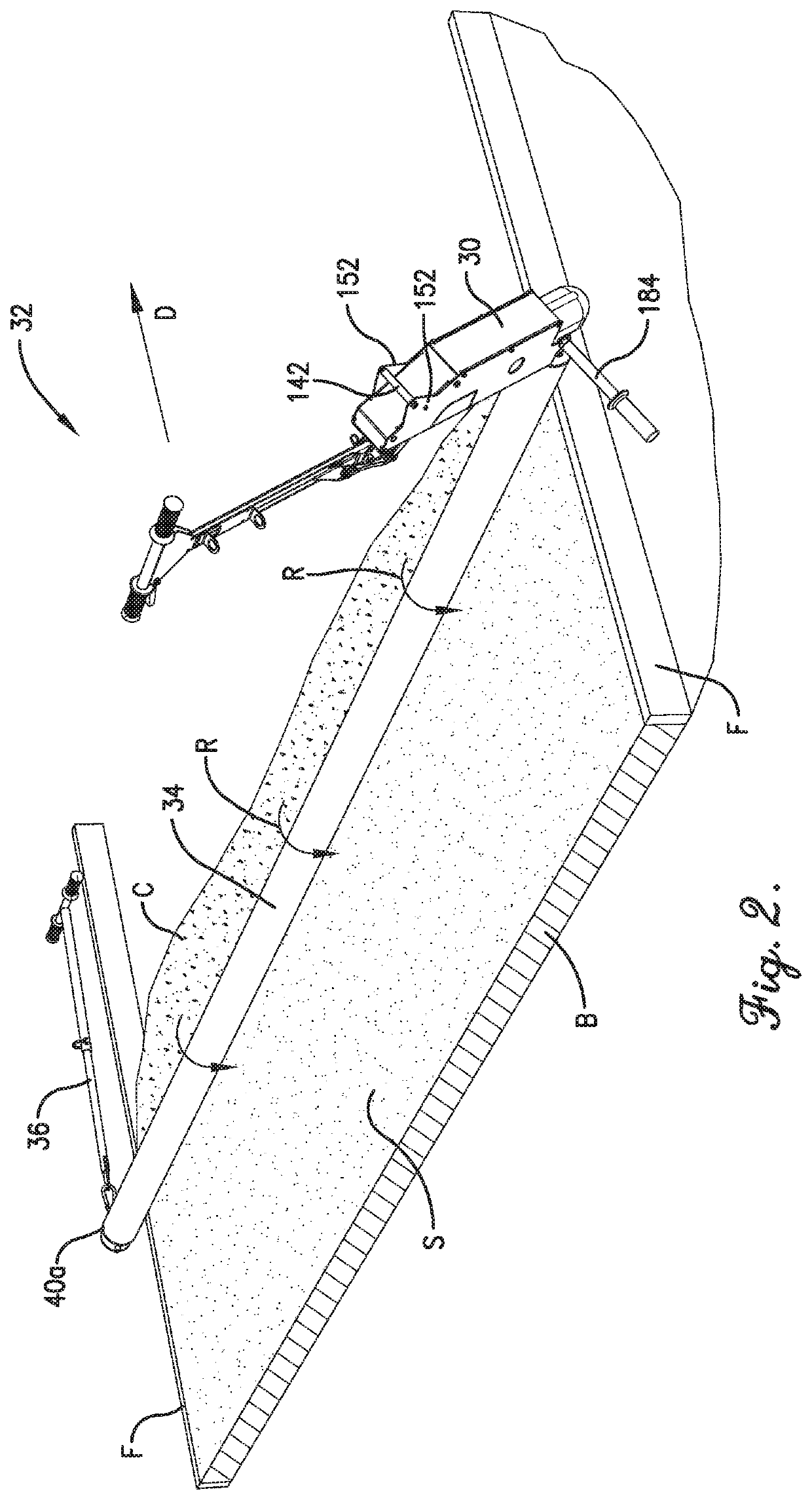
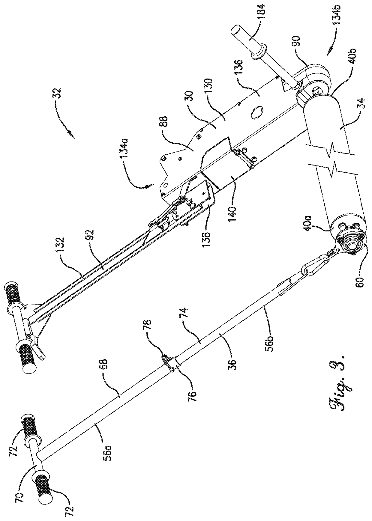
[0042]Turning to FIGS. 1-5, a power unit 30 is provided as part of a powered concrete screed 32. The concrete screed 32 is configured to be manually advanced in a forward direction D along poured concrete C (see FIGS. 1 and 2). Concrete forms F are constructed to define a space to receive the poured concrete C. The concrete forms F hold the poured concrete C within the space as the concrete is graded and finished to form a concrete slab B with a formed surface S.

[0043]In the usual manner, the concrete screed 32 is pulled forwardly across the concrete area to screed the poured concrete C and grade the formed surface S. As the concrete screed 32 is advanced forwardly to grade the surface S, a rotatable concrete forming drum 34 rotates in rotation direction R so that excess concrete along the drum 34 is directed forwardly ahead of the drum 34 (see FIGS. 1 and 2).

[0044]During operation, it will be understood that the concrete screed 32 can be used to remove excess concrete material. For...


PUM


Abstract

A power unit is configured for use as part of a concrete screed and includes a frame, a powered drive, and a mechanical control connection. The frame includes a drive housing and a handle to be grasped by a user, with the handle being configured to facilitate manual advancement of the concrete screed in a forward direction. The handle includes a grip and a relatively shiftable user-operated drive controller. The powered drive is operably supported by the drive housing and is configured to rotate a rotatable concrete forming drum.

Description

CROSS-REFERENCE TO RELATED APPLICATIONS[0001]This application claims the benefit of U.S. Provisional Application Ser. No. 62 / 726,849, filed Sep. 4, 2018, entitled BATTERY POWERED CONCRETE SCREED, which is hereby incorporated in its entirety by reference herein.[0002]This application is being filed contemporaneously with U.S. Nonprovisional application Ser. No. ______ entitled CORDLESS ELECTRICALLY-POWERED CONCRETE SCREED, and U.S. Nonprovisional application Ser. No. ______ entitled DRIVE COUPLER FOR DRILL OUTPUT SHAFT, each of which is hereby incorporated in its entirety by reference herein.BACKGROUND1. Field[0003]The present invention relates generally to concrete equipment used for forming, grading, or screeding concrete. In particular, embodiments of the present invention concern a power unit used as part of a concrete screed and including a mechanical control connection to operate the powered drive of the power unit.2. Discussion of Prior Art[0004]Various types of concrete struc...

Claims


Application Information

Patent Timeline
IPC IPC(8): E01C19/24E04F21/24
CPCE01C19/24E04F21/248E04F15/14F16D1/076F16D1/0894E01C19/187E04G21/10E01C19/29E01C19/262F16D1/108E01C19/201
Inventor PYLE, KRAIG ALLENULMER, SETH NATHANIELARMSTRONG, JOHN ALLEN
Owner CURB ROLLER
Why Eureka
Try Eureka