Mattress edge sewing machine

Inactive Publication Date: 2007-08-30
UNION SPECIAL
View PDF8 Cites 2 Cited by
  • Summary
  • Abstract
  • Description
  • Claims
  • Application Information

AI Technical Summary

Benefits of technology

[0012]According to one aspect, there is provided a mattress edge sewing machine including a frame with a drive shaft rotatably mounted therein and having a material supporting surface, a sewing station defined by a needle bar mounted in the frame for generally vertical reciprocatory movements along a fixed centerline, and a feed mechanism for pulling materials along a generally horizontal direction thereby facilitating advancement of multiple mattress material plies through the sewing station

Problems solved by technology

Mattress edge sewing and taping operations have generally required great manual effort due not only to the size and weight of the mattress but also to the constant compression the operator must apply to the mattress as well as the simultaneous tension the operator must apply to the panels mentioned above.
A longer or a larger lateral distance between the path of the needle and the working edge of the sewing machine throat plate tends to allow materials, being advanced through the sewing station, to become removed from beneath the needle especially when a steel ring is arranged adjacent to the material edge being sewn Moreover, increasing the lateral distance between the path of the needle and the working edge of the throat plate proportionately increases problems involved with sewing a proper seam especially around the four corners of the mattress.
Because the path of the looper crosses the direction of material movement, sewing machines of this design only increase the distance between the path of the needle and the working edge of the throat plate.
Mattress edge sewing machines present a unique combination of characteristics which complicate the design thereof and are contrary to accepted and well known sewin

Method used


Image

  • Mattress edge sewing machine
  • Mattress edge sewing machine
  • Mattress edge sewing machine

Examples


Embodiment Construction

[0046]While the present invention is susceptible of embodiment in multiple forms, there is shown in the drawings and will hereinafter be described a preferred embodiment of the invention, with the understanding the present disclosure sets forth an exemplification of the invention which are not intended to limit the invention to the specific embodiment illustrated and described.

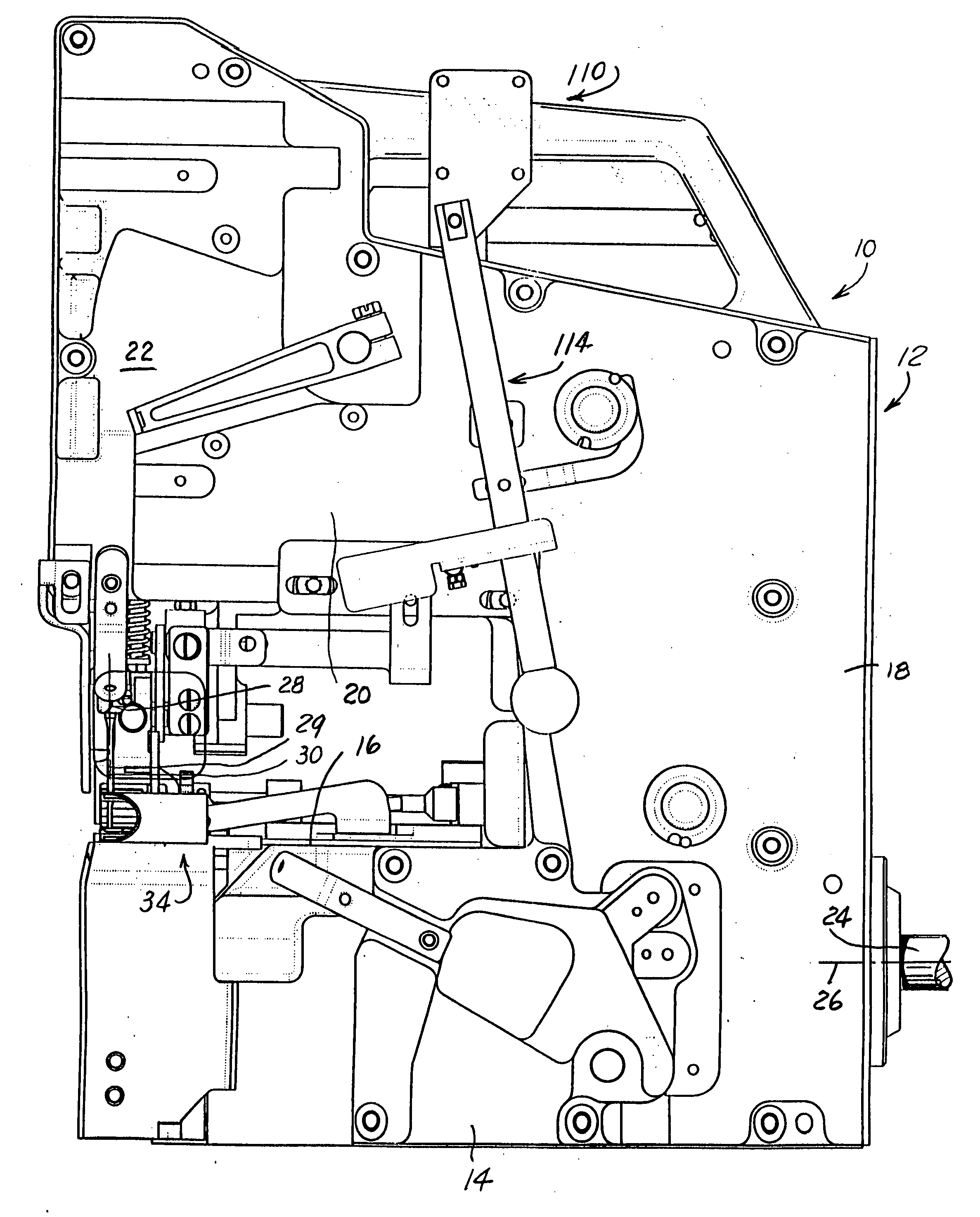
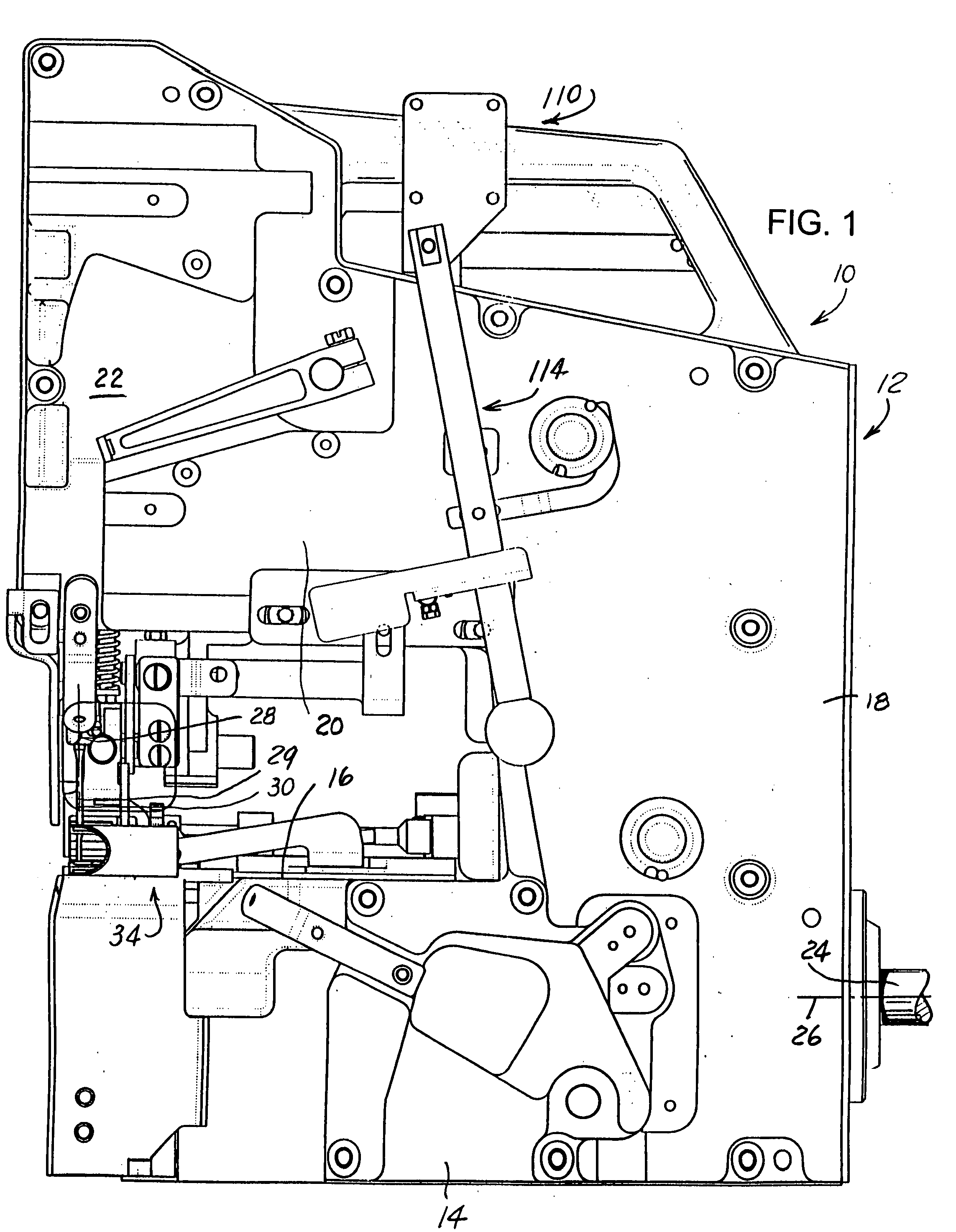
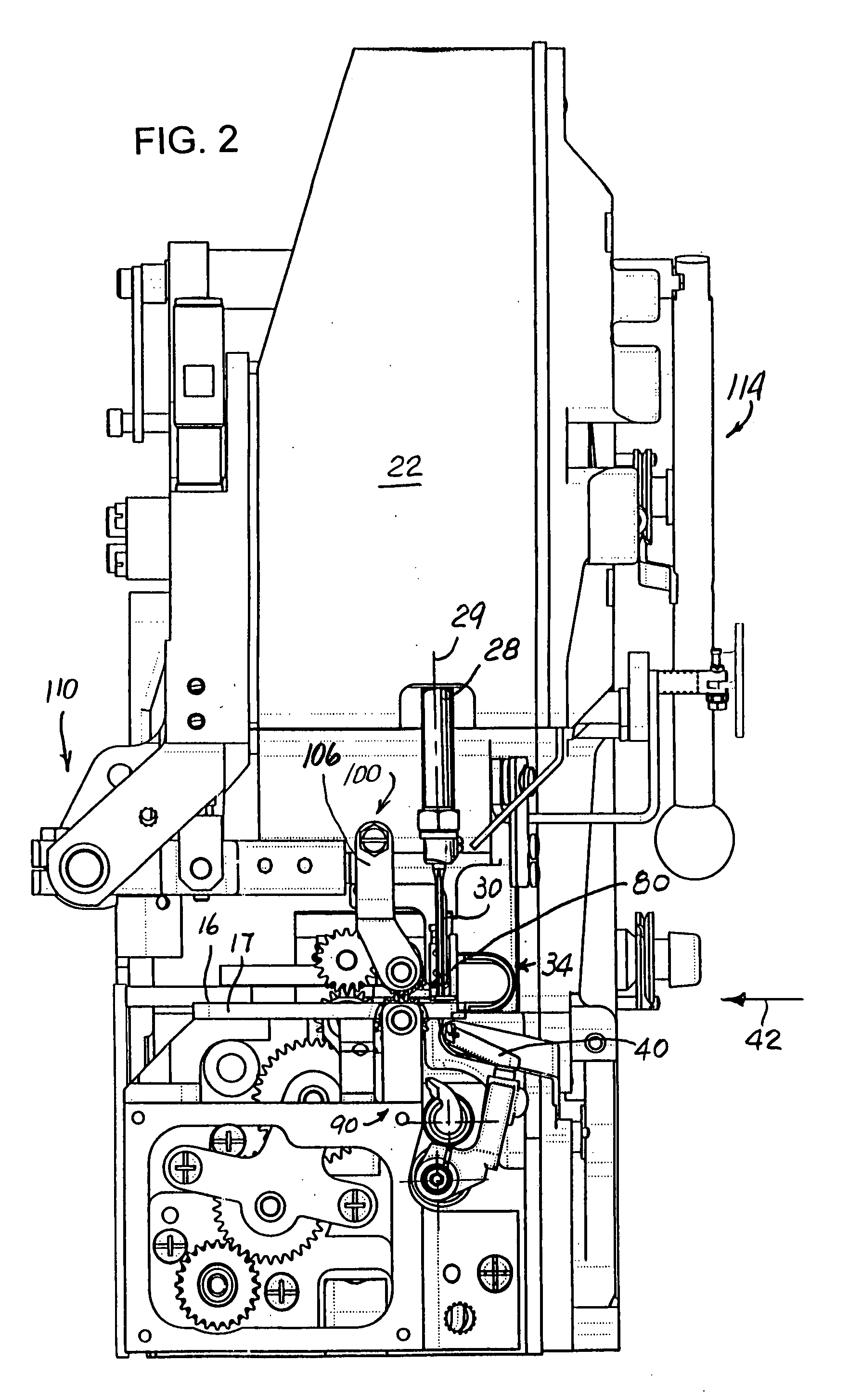
[0047]Referring now to the drawings, wherein like reference numerals indicate like parts throughout the several views, there is schematically shown in FIG. 1 a mattress edge chain-stitch sewing machine, generally identified by reference numeral 10. Sewing machine 10 includes a housing 12 having base portion or bed 14 provided with a work or material supporting surface 16 including a throat plate 17 (FIG. 2), a standard 18 extending vertically from one end of bed 14, and an arm 20 which overlies bed 14 and terminates in a sewing head portion 22. A drive shaft 24 axially extends from and is supported in the bed ...


PUM


Abstract

A mattress edge sewing machine including a frame with a drive shaft rotatably mounted therein and having a material supporting surface, a sewing station defined by a needle bar mounted in the frame for generally vertical reciprocatory movements along a fixed centerline and a feed mechanism for pulling materials along a generally horizontal direction thereby facilitating advancement of multiple mattress material plies through the sewing station of the machine. The feed mechanism includes upper and lower positively driven feed rollers which are continually biased into operable engagement with each other. The feed rollers are arranged in the line of feed of the material and within a range of about 0.4 inch to about 1.0 inch rearwardly of the needle bar centerline whereby facilitating advancement of material through a sewing station on the machine and especially around four corners of a mattress being sewn. The needle bar is moved in timed relation relative to the movements of the looper, and with the needle bar traversing a distance in a single vertical direction at a ratio greater than 2:1 relative to the distance in a single lateral direction traversed by the looper.

Description

CROSS REFERENCE TO RELATED APPLICATION[0001]This patent application claims the benefit of provisional patent application Ser. No. 60 / 777,664; filed Feb. 28, 2006.FIELD OF THE INVENTION[0002]The present invention generally relates to sewing machines and, more particularly to a mattress edge sewing machine having a roller feed mechanism for intermittently advancing material through stitch forming instrumentalities on the sewing machine including a thread carrying needle which travels at a ratio greater than 2:1 relative to a thread carrying looper arranged in operable combination with the needle.BACKGROUND OF THE INVENTION[0003]Specialized edge sewing and taping machines sew and secure peripheral edges of upper and lower mattress panels or a mattress cushion to the side panels thereof. During a mattress sewing operation, a sewing machine moves around a support relative to the mattress and performs a sewing operation about the periphery of the mattress. Chain-stitch sewing machines cap...

Claims


Application Information

Patent Timeline
IPC IPC(8): D05B11/00
CPCD05B11/005D05B73/12D05B55/06D05B27/14
Inventor FABER, MICHAEL P.TURNER, BOB C.
Owner UNION SPECIAL
Why Eureka
Try Eureka