In-facility transmission system, in-facility transmission method, and base station

a transmission system and transmission method technology, applied in active radio relay systems, network topologies, electrical apparatus, etc., can solve the problems of deteriorating communication quality, reducing the power of signals when signals pass through blocking objects in propagation paths, and ensuring desired communication quality, so as to achieve stable radio communication.

Inactive Publication Date: 2020-06-11
PANASONIC INTELLECTUAL PROPERTY MANAGEMENT CO LTD
View PDF96 Cites 0 Cited by
  • Summary
  • Abstract
  • Description
  • Claims
  • Application Information

AI Technical Summary

Benefits of technology

[0016]According to the disclosure, it is possible to secure desired communication quality in relay for data transmission between base stations and to realize stable radio communication, in a facility in which the base stations are provided in different closed spaces.

Problems solved by technology

Therefore, the power of a signal when the signal passes through a blocking object in a propagation path is largely reduced, and communication quality (for example, throughput and packet error rate) is largely deteriorated.
Therefore, there are problems in that it may or may not possible to secure desired communication quality in a propagation path between base stations provided in different closed spaces, and it may be difficult to form a relay link (that is, radio communication link) for data transmission.

Method used


Image

  • In-facility transmission system, in-facility transmission method, and base station
  • In-facility transmission system, in-facility transmission method, and base station
  • In-facility transmission system, in-facility transmission method, and base station

Examples


exemplary embodiment 1

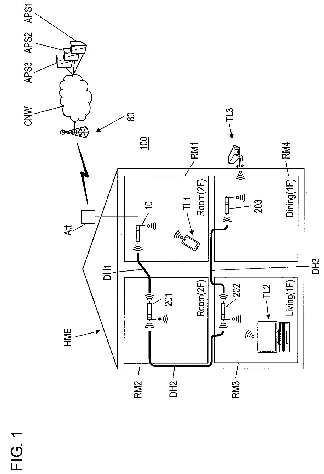
[0036]FIG. 1 is a diagram illustrating an example of a specific system configuration in which in-facility transmission system 100 according to Exemplary Embodiment 1 is disposed in private house HME.

[0037]In-facility transmission system 100 in Exemplary Embodiment 1 includes master base station 10 connected to antenna Att, first slave base station 201, second slave base station 202, third slave base station 203, external base station 80, and application servers APS1, APS2, and APS3. The in-facility transmission system in the following exemplary embodiments is assumed to be incorporated into the known cellular network system.

[0038]Private house HME illustrated in FIG. 1 is, for example, a two-floor residence and has a plurality of closed spaces. Private house HME may be a three-floor residence as in Exemplary Embodiment 3 described later, and may be a residence of floors more than the three floors. For example, the closed space is provided to be distinguishable from another closed sp...

exemplary embodiment 2

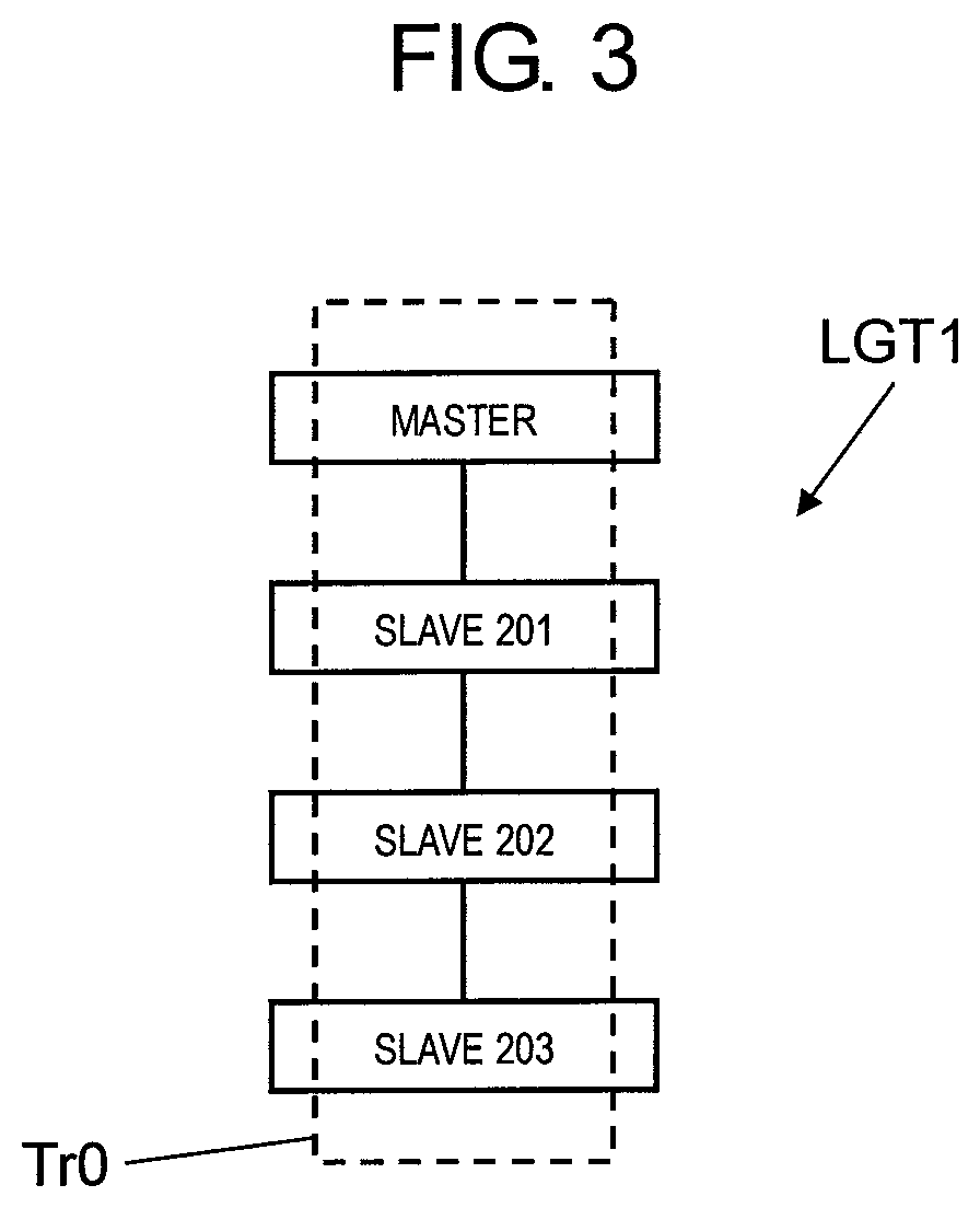
[0095]In Exemplary Embodiment 1, master base station 10, slave base station 201, slave base station 202, and slave base station 203 are connected to each other through dielectric waveguides DH1, DH2, and DH3 in a one-stroke manner. In Exemplary Embodiment 2, an example in which master base station 10, slave base station 201, slave base station 202, and slave base station 203 are connected to each other in a ring shape through dielectric waveguides DH1, DH2, DH3, and DH4 will be described.

[0096]FIG. 5 is a diagram illustrating an example of a specific system configuration in which in-facility transmission system 100A according to Exemplary Embodiment 2 is disposed in a private house.

[0097]In-facility transmission system 100A in Exemplary Embodiment 2 includes master base station 10A connected to antenna Att, first slave base station 401L, second slave base station 402, third slave base station 401R, external base station 80, and application servers APS1, APS2, and APS3. In in-facilit...

exemplary embodiment 3

[0158]In Exemplary Embodiment 3, an example in which a multi-hop relay route is changed when a problem occurs in, for example, any slave base station or a dielectric waveguide which is connected to the slave base station in radio among the master base station and the plurality of slave base stations connected in a ring shape, such that using the slave base station or the dielectric waveguide in which the problem occurs is avoided will be described. Hereinafter, in order to make the descriptions easy to understand, an example in which a problem (for example, abnormality such as a failure) occurs in any slave base station will be described. However, the following descriptions can be similarly applied to a case where a problem occurs in a dielectric waveguide connected to the slave base station in radio.

[0159]FIG. 9 is a diagram illustrating an example of a specific system configuration in which in-facility transmission system 100B according to Exemplary Embodiment 3 is disposed in a p...


PUM


Abstract

Desired communication quality in relay for data transmission is secured, and stable radio communication is realized. An in-facility transmission system is disposed in a facility with a plurality of closed spaces, and includes a master base station that is disposed in a first closed space and performs a radio communication with an external base station provided outside the facility and a first slave base station that is disposed in a second closed space different from the first closed space and performs a radio communication with the master base station. The first closed space and the second closed space are connected to each other through a first radio waveguide capable of reducing a propagation loss of a radio wave in the radio communication between the master base station and the first slave base station.

Description

TECHNICAL FIELD[0001]The present disclosure relates to an in-facility transmission system and an in-facility transmission method for performing data transmission by radio communication between a plurality of base stations in a facility, and to a base station used in the in-facility transmission system.BACKGROUND ART[0002]In order to transmit large data by radio communication, a high frequency band (for example, using a high super high frequency (SHF) band of 6 to 30 GHz or an extremely high frequency band (EHF) of 30 to 300 GHz is examined, for example, in a 5G (fifth generation mobile communication system) radio network. In such a high frequency band, a radio wave propagation loss by a blocking object such as an obstacle is large. Assuming a high-frequency radio communication in a facility such as a house or a building, it may be difficult to perform radio communication with favorable communication quality in the facility. In the 5G radio network, it is also examined to incorporate...

Claims


Application Information

Patent Timeline
Patent Type & Authority Applications(United States)
IPC IPC(8): H04W16/32H04W4/33
CPCH04W84/045H04W4/33H04W92/20H04W16/32H04B5/00H04B7/15H04W16/26
Inventor ASANO, HIROAKIKANEMOTO, HIDEKIKATO, OSAMU
Owner PANASONIC INTELLECTUAL PROPERTY MANAGEMENT CO LTD
Why Eureka
Try Eureka