Time-of-flight depth measurement using modulation frequency adjustment

a modulation frequency and depth measurement technology, applied in the field of image sensors, can solve the problems of insufficient use of a single low frequency to achieve a requisite depth quality, inflict some degree of quality degradation in the measurement, and not realize the desired depth quality, etc., to achieve efficient target accuracy, increase modulation frequency, and high depth accuracy

Active Publication Date: 2020-11-05
SAMSUNG ELECTRONICS CO LTD
View PDF6 Cites 3 Cited by
  • Summary
  • Abstract
  • Description
  • Claims
  • Application Information

AI Technical Summary

Benefits of technology

[0006]Embodiments of the inventive concept relate to an iterative approach to achieve high depth accuracy in ToF measurements, in which measurements may be repeated using progressively increasing modulation frequencies. Each successive modulation frequency may be calculated based on a statistical distribution of the previous measurement, to efficiently arrive at a target accuracy.

Problems solved by technology

Consequently, the use of a single low frequency may not suffice to achieve a requisite depth quality.
These techniques, however, may inflict some degree of quality degradation in the measurement, or may not realize a desired depth quality.

Method used


Image

  • Time-of-flight depth measurement using modulation  frequency adjustment
  • Time-of-flight depth measurement using modulation  frequency adjustment
  • Time-of-flight depth measurement using modulation  frequency adjustment

Examples


Embodiment Construction

[0024]The following description, with reference to the accompanying drawings, is provided to assist in a comprehensive understanding of certain exemplary embodiments of the inventive concept disclosed herein for illustrative purposes. The description includes various specific details to assist a person of ordinary skill the art with understanding the inventive concept, but these details are to be regarded as merely illustrative. For the purposes of simplicity and clarity, descriptions of well-known functions and constructions may be omitted when their inclusion may obscure appreciation of the inventive concept by a person of ordinary skill in the art.

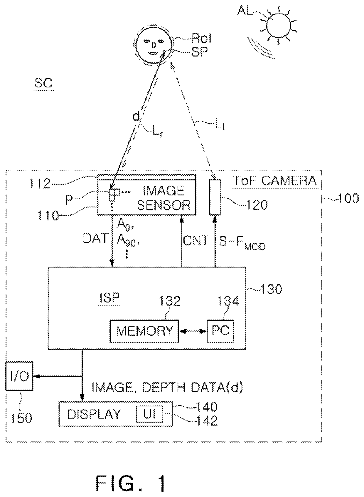
[0025]FIG. 1 is a block diagram showing elements and signals within a ToF camera, 100, according to an embodiment of the inventive concept. ToF camera 100 may include an image sensor 110, an illuminator 120, image signal processor (ISP) 130, a lens 112, a display 140 and an input / output (I / O) interface 150. ToF camera 100 may include ca...


PUM


Abstract

In a method for time-of-flight (ToF) based measurement, a scene is illuminated using a ToF light source modulated at a first modulation frequency FMOD(1). While the light is modulated using FMOD(1), depths are measured to respective surface points within the scene, where the surface points are represented by a plurality of respective pixels. At least one statistical distribution parameter is computed for the depths. A second modulation frequency FMOD(2) higher than FMOD(1) is determined based on the at least one statistical distribution parameter. The depths are then re-measured using FMOD(2) to achieve a higher depth accuracy.

Description

TECHNICAL FIELD[0001]The present disclosure relates generally to image sensors and more particularly to time-of-flight cameras and methods for improving the quality of distance measurements to surfaces in a scene.DISCUSSION OF THE RELATED ART[0002]“Indirect” time-of-flight (ToF) depth measuring systems use a light source to emit a modulated light wave, where the modulating signal may be sinusoidal, a pulse train, or other periodic waveform. A ToF sensor detects this modulated light reflected from surfaces in the observed scene. From the measured phase difference between the emitted modulated light and the received modulated light, the physical distance between the ToF sensor and the scene's surfaces can be calculated. For a given distance, the measured phase shift is proportional to the modulating frequency.[0003]In ToF vernacular, “depth” of a surface point is often used loosely to mean the distance from the surface point to a reference point of the ToF sensor, rather than a z dire...

Claims


Application Information

Patent Timeline
Patent Type & Authority Applications(United States)
IPC IPC(8): G06T7/521H04N5/225G06K9/00G01S17/89G01S17/10
CPCG06T2207/30201G01S17/10G06T7/521G01S17/89H04N5/2256G06K9/00228G06T2207/10028G06T2207/20104G06T2207/10152G06T2207/10048G01S17/32G01S17/894G01S7/497H04N5/2226H04N23/56G06V40/161
Inventor BITAN, GALYAM, ROYKOLTUN, GERSHI
Owner SAMSUNG ELECTRONICS CO LTD
Why Eureka
Try Eureka