
Image vision processing method, device and equipment

a processing method and image technology, applied in the field of image processing, can solve problems such as information determination, pixel points are wrong, and it is difficult to distinguish between non-event pixel points,

Active Publication Date: 2020-02-04
SAMSUNG ELECTRONICS CO LTD
View PDF27 Cites 2 Cited by
  • Summary
  • Abstract
  • Description
  • Claims
  • Application Information

AI Technical Summary

Benefits of technology

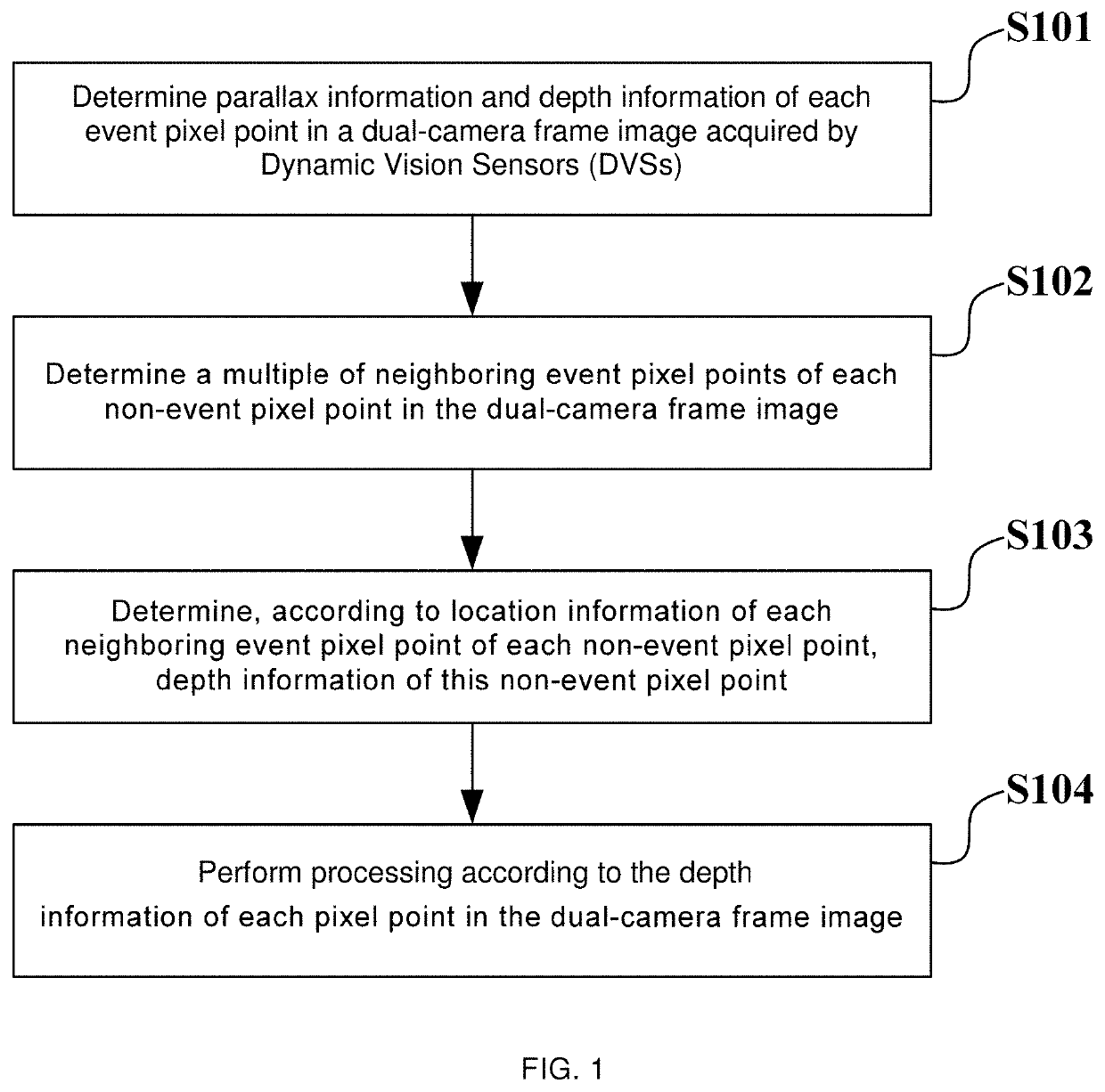
[0009]In view of the deficiencies in the related art, the present exemplary embodiments provide an image vision processing method, device and equipment in order to address the challenges regarding low accuracy of depth information of non-event pixel points in the related art and improve the accuracy of depth information of non-event pixel points.
[0016]In the exemplary embodiments, the depth information of non-event pixel points occupying most regions of a frame image is determined according to the location information of multiple neighboring event pixel points. Since the non-event pixel points do not participate in the matching of pixel points, the problem in the related art that non-event pixel points are likely to be mismatched or unable to be matched is completely avoided. Even if it is difficult to distinguish between the non-event pixel points in terms of illumination intensity, contrast and texture or the non-event pixel points are occluded, in the exemplary embodiments, the depth information of the non-event pixel points can be accurately determined according to the location information of neighboring event pixel points, so that the accuracy of the depth information of the non-event pixel points occupying most regions of the frame image is improved. Consequently, the accuracy of the depth information of pixel points in the frame image is improved as a whole, and it is convenient to perform subsequent operations based on the depth information of the pixel points in the frame image. Moreover, in the exemplary embodiments, the operations of calculating the parallax of the non-event pixel points are omitted, so that the efficiency is improved.

Problems solved by technology

However, the DVS generates a small amount of (i.e., sparse) event pixel points and the event pixel points generated by the left and right DVS cameras are inconsistent in distribution and amount, or more.
On one hand, since the non-event pixel points have a small change in contrast, and there is a little difference in contrast between the non-event pixel points particularly in a scene with a high illumination intensity (e.g., backlight) or a low illumination intensity (e.g., at night or in a dark room), it is difficult to distinguish between the non-event pixel points.
Therefore, in the existing image vision processing method, when performing matching between non-event pixel points or between event pixel points and non-event pixel points in the left-camera and right-camera frame images, it is very likely to result in mismatching.
On the other hand, when there is a repetitive texture structure (e.g., checkerboard texture) in a frame image, due to the repetition of the texture, a non-event pixel point in a camera frame image have a plurality of matchable pixel points in the other camera frame image, so that it is very likely to result in mismatching.
Undoubtedly, the depth information determined according to the mismatched non-event pixel points is wrong, and the non-event pixel points are very likely to become noise points.
As a result, the accuracy of the depth information of pixel points in the whole frame image is reduced greatly.
Consequently, subsequent processing operations based on the depth information of pixel points in the frame image are adversely impacted, or even the subsequent processing operations based on the depth information of the pixel points fails.
However, due to the occlusion by different objects to be shot in some scenes (e.g., close shooting or macro shooting), the dual-camera frame images are not completely consistent.
Therefore, in the existing image vision processing methods, the depth information of these unmatchable non-event pixel points cannot be determined, and these non-event pixel points are very likely to become noise points.
As a result, the accuracy of the depth information of pixel points in the whole frame image is reduced greatly.
Consequently, subsequent processing operations based on the depth information of pixel points in the frame image are adversely impacted, or even the processing operations based on the depth information of the pixel points fails.

Method used


Image

  • Image vision processing method, device and equipment
  • Image vision processing method, device and equipment
  • Image vision processing method, device and equipment

Examples


Embodiment Construction

[0024]Exemplary embodiments will be described in detail hereinafter. The examples of these exemplary embodiments have been illustrated in the accompanying drawings throughout which same or similar reference numerals refer to same or similar elements or elements having same or similar functions. The embodiments described with reference to the accompanying drawings are illustrative, merely used for explaining the present invention and should not be regarded as any limitations thereto.

[0025]It should be understood by one person of ordinary skill in the art that singular forms “a”, “an”, “the”, and “said” may be intended to include plural forms as well, unless otherwise stated. It should be further understood that terms “comprise / comprising” used in this specification specify the presence of the stated features, integers, steps, operations, elements and / or components, but not exclusive of the presence or addition of one or more other features, integers, steps, operations, elements, comp...


PUM


Abstract

Exemplary embodiments provide an image vision processing method, device and equipment and relate to: determining parallax and depth information of event pixel points in a dual-camera frame image acquired by Dynamic Vision Sensors; determining multiple neighboring event pixel points of each non-event pixel point in the dual-camera frame image; determining, according to location information of each neighboring event pixel point of each non-event pixel point, depth information of the non-event pixel point; and performing processing according to the depth information of each pixel point in the dual-camera frame image. Since non-event pixel points are not required to participate in the matching of pixel points, even if it is difficult to distinguish between the non-event pixel points or the non-event pixel points are occluded, depth information of the non-event pixel points can be accurately determined according to the location information of neighboring event pixel points.

Description

CROSS-REFERENCE TO RELATED APPLICATIONS[0001]This application claims the benefit of Chinese Patent Application No. 201611033320.2, filed on Nov. 14, 2016, in the State Intellectual Property Office of the People's Republic of China, the disclosure of which is incorporated herein in its entirety by reference.TECHNICAL FIELD[0002]Exemplary embodiments consistent with the present invention relate to the technical field of image processing, and in particular to an image vision processing method, device and equipment.BACKGROUND ART[0003]A Dynamic Vision Sensor (DVS) is a novel Complementary Metal Oxide Semiconductor (CMOS) image sensor. Different from images generated by a conventional CMOS or Charged-coupled Device (CCD) sensor, the DVS can generate events according to the change in illumination intensity of a scene. The DVS generates a DVS image by using the change in contrast of pixel points which exceeds a preset threshold due to the change in illumination intensity, as event pixel ev...

Claims


Application Information

Patent Timeline
Patent Type & Authority Patents(United States)
IPC IPC(8): G06K9/00G06T7/593H04N13/128
CPCH04N13/128G06T7/593G06T2207/10012G06T2207/10028H04N2013/0081H04N13/239
Inventor ZOU, DONGQINGSHI, FENGLIU, WEIHENGQIAN, DEHENGRYU, HYUNSURK ERICLI, JIAXU, JINGTAOPARK, KEUN JOOWANG, QIANGSHIN, CHANGWOO
Owner SAMSUNG ELECTRONICS CO LTD
Learn More