Method for controlling current path range by using electric field, and electronic circuit

Active Publication Date: 2021-08-12
VMEMORY CORP
View PDF0 Cites 0 Cited by
  • Summary
  • Abstract
  • Description
  • Claims
  • Application Information

AI Technical Summary

Benefits of technology

[0040]A method of controlling a current path range and an electric circuit acc

Problems solved by technology

Due to this trend, there is a limitation in implementing and controlling electric circ

Method used


Image

  • Method for controlling current path range by using electric field, and electronic circuit
  • Method for controlling current path range by using electric field, and electronic circuit
  • Method for controlling current path range by using electric field, and electronic circuit

Examples


Embodiment Construction

Technical Problem

[0008]The present disclosure is directed to providing a method of controlling a current path range and an electric circuit, which are easily applicable to various applications.

Solution To Problem

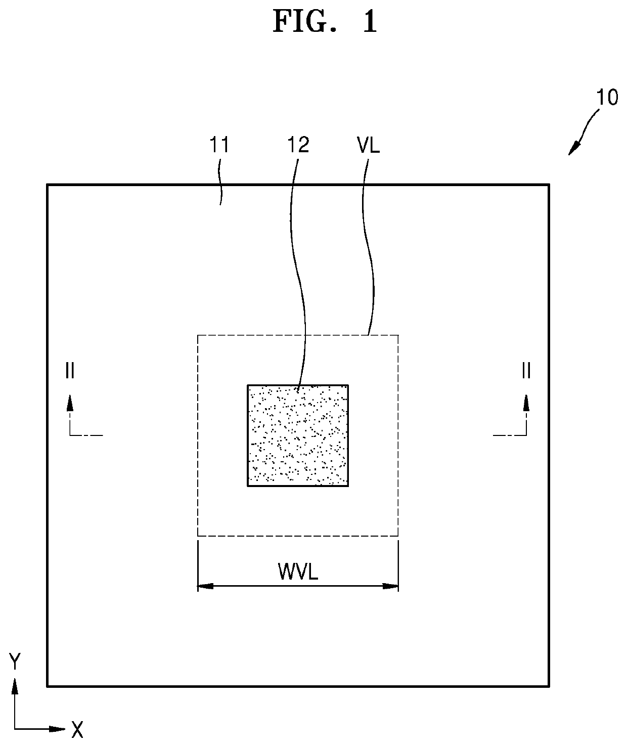
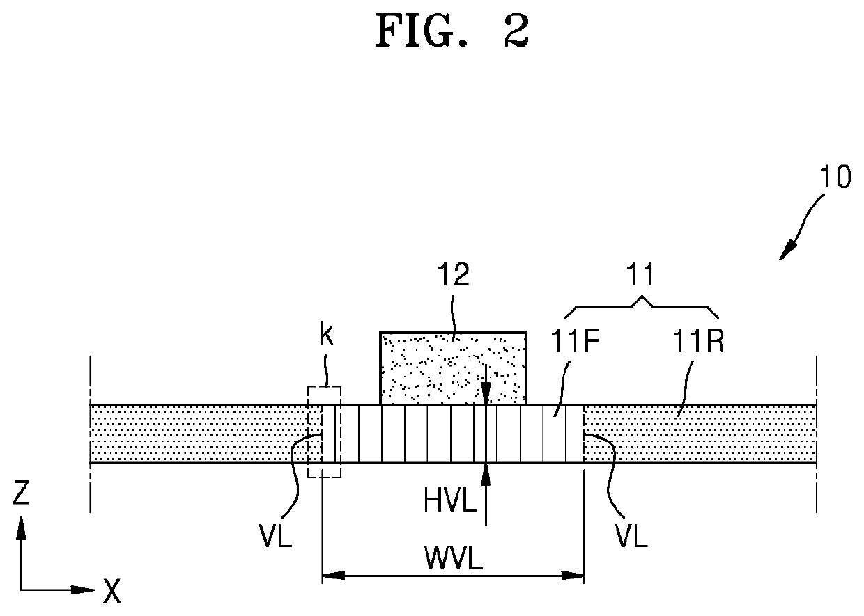
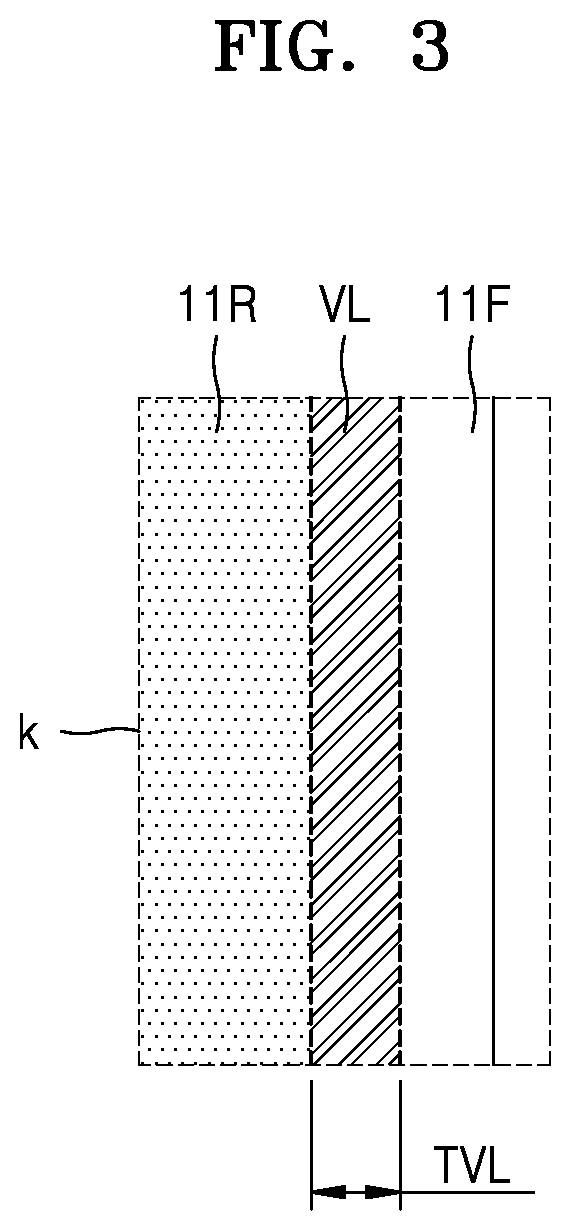
[0009]One aspect of the present disclosure provides a method of controlling a current path range using an electric field is disclosed, the method including applying an electric field to an active layer including a spontaneous polarization material through an application electrode disposed adjacent to the active layer to form a polarization region of the active layer, and forming a variable low resistance region corresponding to a boundary of the polarization region, wherein the variable low resistance region is a region of the active layer having a lower electrical resistance than another region of the active layer adjacent to the variable low resistance region and allows an electrical path to be formed.

[0010]In an embodiment, the forming of the variable low resistance regio...


PUM


Abstract

A method of controlling a current path range using an electric field is disclosed, and the method of controlling a current path range includes applying an electric field to an active layer including a spontaneous polarization material through an application electrode disposed adjacent to the active layer to form a polarization region of the active layer, and forming a variable low resistance region corresponding to a boundary of the polarization region, wherein the variable low resistance region is a region of the active layer having a lower electrical resistance than another region of the active layer adjacent to the variable low resistance region and allows an electrical path to be formed.

Description

TECHNICAL FIELD[0001]The present disclosure relates to a method of controlling a current path range using an electric field and a method of controlling a current path range of an electric circuit.BACKGROUND ART[0002]As technology has developed and the interest of people in the convenience of life is increased, the development of various electronic products has been actively attempted.[0003]In addition, the electronic products are becoming smaller in size and highly integrated and are increasingly being used in a wide range of places.[0004]Such electronic products include various electric elements, and, for example, include a central processing unit (CPU), a memory, and other various electric elements. The electric elements may include various types of electric circuits.[0005]Electric elements are used, for example, not only in computers and smartphones but also in products in various fields, such as home sensor devices for Internet of Things (loT) and bioelectronic devices for ergon...

Claims


Application Information

Patent Timeline
IPC IPC(8): H02N99/00
CPCH02N99/00G11C11/22H01C10/06H01C10/50G11C11/2275
Inventor SON, JONG HWASON, JONG YEOG
Owner VMEMORY CORP
Why Eureka
Try Eureka