Corrosion testing device

a testing device and corrosion technology, applied in the direction of instruments, borehole/well accessories, surveys, etc., can solve the problems of local disruption of the strength inability to accurately represent the fluid flow along the pipe sections used in the wellbore, and complex construction, etc., to achieve the effect of simple construction, easy and cheap production, and negative affecting the strength and stiffness of the sucker rod

Active Publication Date: 2021-08-26
TENARIS CONNECTIONS
View PDF0 Cites 1 Cited by
  • Summary
  • Abstract
  • Description
  • Claims
  • Application Information

AI Technical Summary

Benefits of technology

The corrosion testing device for a sucker rod has at least one coupon holder that allows the sucker rod to be constructed with pipe sections, reducing risks of failure. The coupon holder is placed on the outer rod surface, making space available within the well bore for multiple coupons. The device also prevents damage to the wellbore and well tubing when the sucker rod is moved within it. The technical effects of this invention include construction of a stronger and stiffer sucker rod, efficient corrosion testing, and reduced risk of failure.

Problems solved by technology

In particular, it does not accurately represent the fluid flow along pipe sections used in the wellbore, such as the sucker rod or the well tubing.
A further drawback of the known coupon holder is that it has a complex construction which is relatively difficult and expensive to produce.
Furthermore, the known coupon holder with its chamber and fluid flow ports in the outer wall forms a local disruption in the strength of the sucker rod.
This creates a higher risk of failure.
In addition to this, it requires a relatively labour intensive operation to assemble the known coupon holder in the sucker rod.
Removing the known coupon holder from the sucker rod is also relatively labour intensive.
Moreover, the known coupon holder can only be used with one coupon at the time.

Method used


Image

  • Corrosion testing device
  • Corrosion testing device
  • Corrosion testing device

Examples


Embodiment Construction

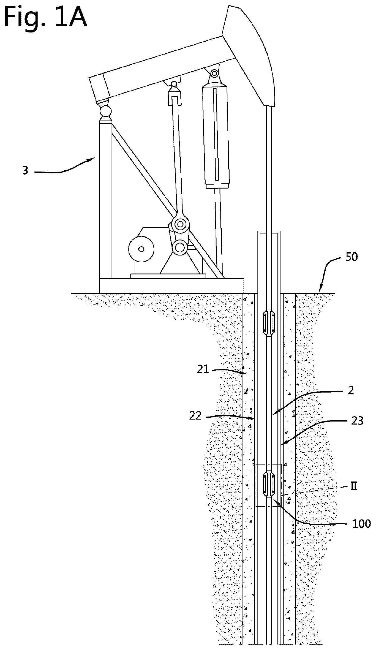
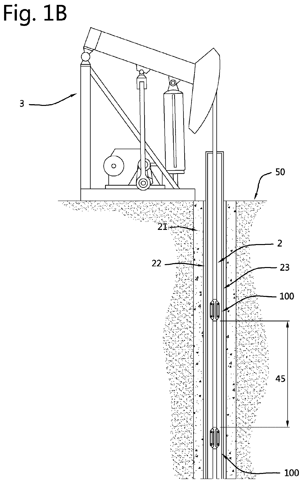
[0073]The FIGS. 1A and B show an embodiment of the pump system 3 according to the invention. The pump system 3 is used to pump hydrocarbon fluids out of a hydrocarbon well via a wellbore 21 located in the ground 50. The wellbore 21 comprises an outer well casing 22 surrounding an inner well tubing 23. A sucker rod 2 is located in the wellbore 21, more specifically in the well tubing 23. A piston (not shown) configured to pump the hydrocarbon fluid out of the well bore is attached to the lower end of the sucker rod 2. The pump system 3 is a pump jack system which moves up and down as shown in the FIGS. 1A and B. This way, the sucker rod 2 and piston are moved within the well tubing 23 in a reciprocal manner. In an alternative embodiment, the pump system 3 is a progressing cavity pump system configured to rotate the sucker rod 2 within the well bore, more specifically the well tubing 23.

[0074]Multiple corrosion testing devices 100 are attached to the sucker rod 2. The corrosion testin...


PUM


Abstract

A corrosion testing device comprising a coupon holder for a sucker rod of a pump system and at least one coupon for corrosion testing, wherein the coupon holder comprises a holder body having an outer body surface and an inner contact surface, which inner contact surface is placeable on an outer rod surface of the sucker rod and defines a longitudinal body axis of the holder body, the at least one coupon is attached to the holder body and positioned at the outer body surface and at a radial coupon distance from the longitudinal body axis, the outer body surface comprises at least one guiding surface part located at a radial surface distance from the longitudinal body axis, and the radial surface distance is larger than the radial coupon distance.

Description

FIELD OF THE INVENTION[0001]A pump system is used to pump hydrocarbon fluids out of a hydrocarbon well via a wellbore located in the ground. In general, the wellbore comprises an outer well casing surrounding an inner well tubing. The pump system moves a sucker rod within the well tubing. Sucker rods are used in different types of pump systems, such as pump jack systems wherein the sucker rod is reciprocated and progressing cavity pump systems wherein the sucker rod is rotated.[0002]The invention relates to a corrosion testing device comprising a coupon holder for a sucker rod of a pump system and at least one coupon for corrosion testing. In use, the coupon holder is attached to the sucker rod and located in the wellbore to move along with the sucker rod.[0003]Such a corrosion testing device is known from U.S. Pat. No. 5,095,977. Said corrosion testing device has a coupon holder with an upper and lower threaded connection holding the coupon holder between two threaded pipe sections...

Claims


Application Information

Patent Timeline
IPC IPC(8): G01N17/04
CPCG01N17/046G01N17/043E21B17/1071E21B43/127E21B47/006
Inventor NICOLINO, MIGUEL SANDRO
Owner TENARIS CONNECTIONS
Why Eureka
Try Eureka