

Brushless electric motor
a brushless electric motor and motor body technology, applied in the direction of mechanical energy handling, dynamo-electric machines, supports/encloses/casings, etc., can solve the problems of increasing assembly costs and making assembly considerably more difficult, and achieve the effect of easy assembly/disassembly
- Summary
- Abstract
- Description
- Claims
- Application Information
AI Technical Summary
Benefits of technology
Problems solved by technology
Method used
Image

Examples
Embodiment Construction
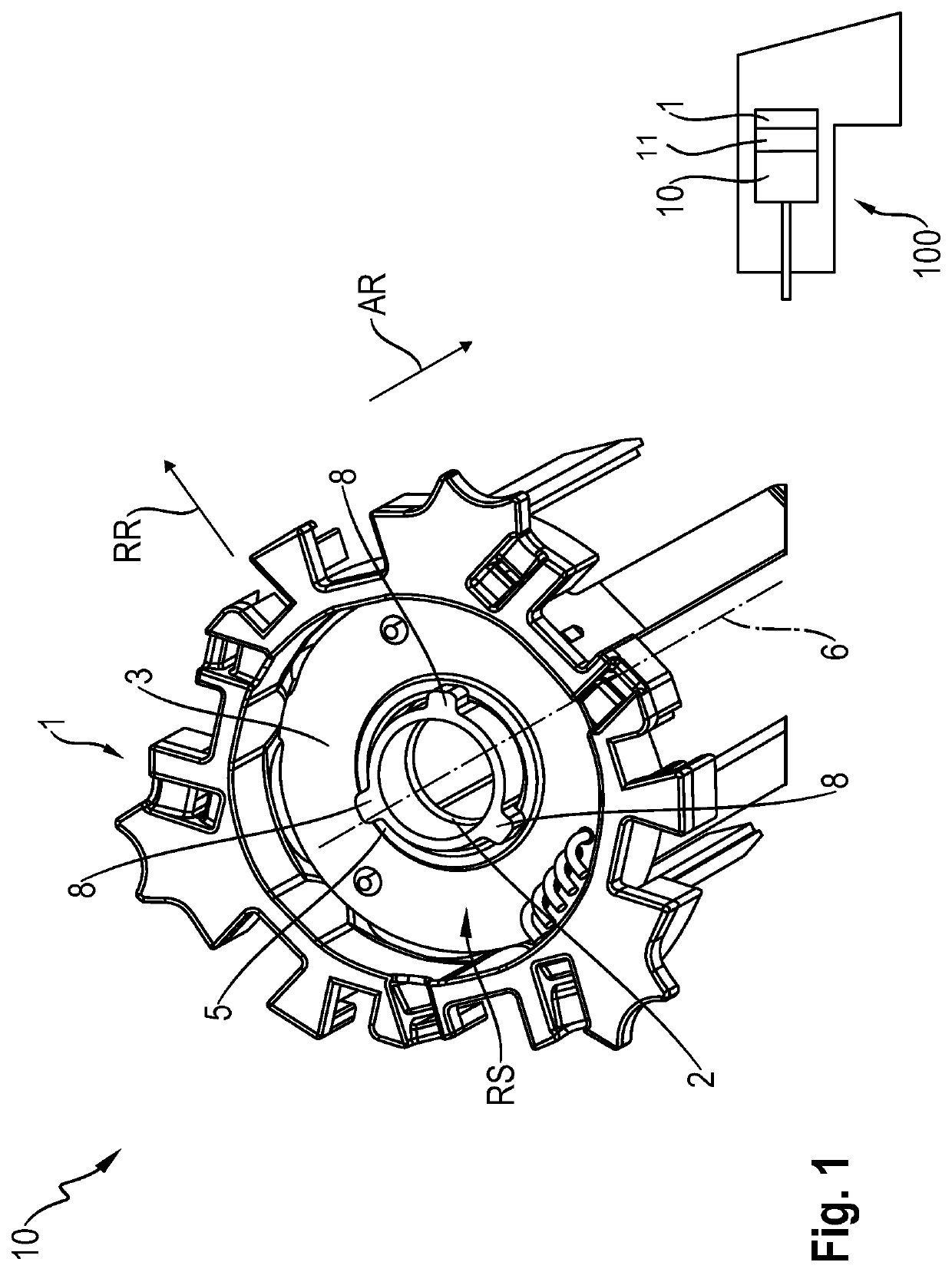
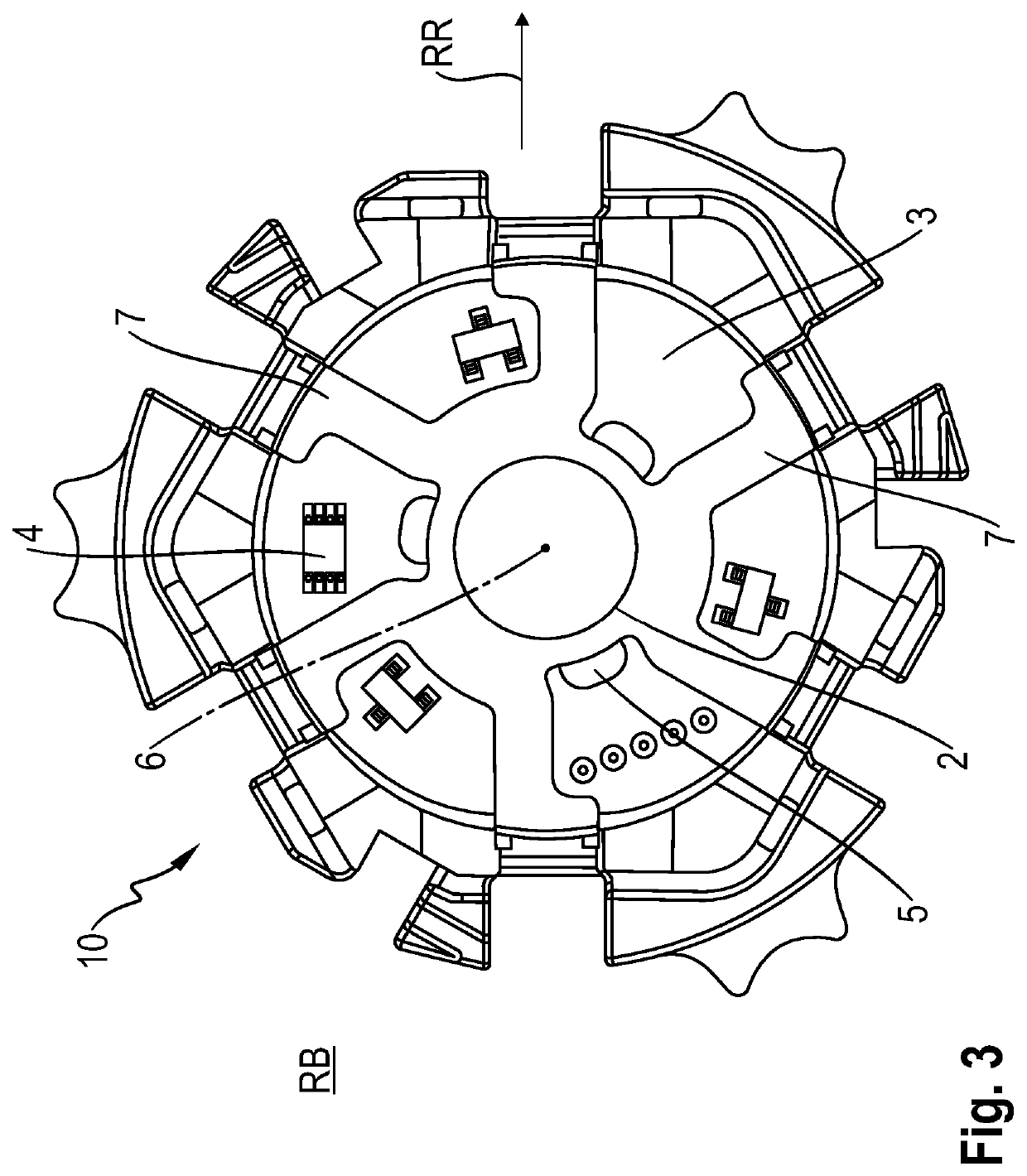
[0016]A preferred exemplary embodiment of a brushless electric motor 10 according to the invention looking at the side RS that faces away from the rotor is depicted in FIG. 1. The electric motor 10 has an end plate 1 and a Hall board 3 which is arranged on the end plate 1. In the exemplary embodiment depicted in the present case, the end plate 10 is a B end plate, that is to say the end plate which is situated opposite the drive side of the electric motor 10. For reasons of clarity, the electric motor 10 is not shown in its entirety, that is to say, in particular, a stator winding or a stator core (apart from a few stator segments which are connected to the end plate 1) is not depicted in FIG. 1.
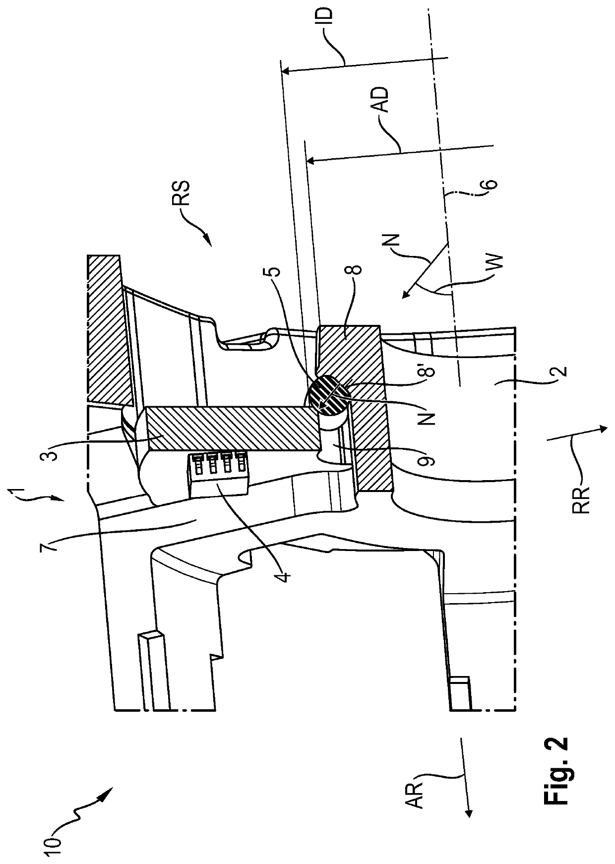
[0017]According to the invention, the Hall board 3 is axially fixed, that is to say fixed in the axial direction AR, to the end plate 1 by means of an elastic O-ring 5. In the present case, the Hall board 3 is axially fixed to the end plate 1 exclusively by means of the O-ring 5. The Hall bo...
PUM
 Abstract
Description
Claims
Application Information