Electronic device comprising microphone coupling structure

a technology of electronic devices and coupling structures, which is applied in the direction of electrical transducers, mouthpiece/microphone attachments, transducer details, etc., can solve the problems of increased noise generation, increased sound loss, and longer length of the acoustic duct between the microphone hole and the microphone, so as to improve the quality of the exterior face and facilitate assembly/disassembly

Inactive Publication Date: 2021-11-11
SAMSUNG ELECTRONICS CO LTD
View PDF0 Cites 0 Cited by
  • Summary
  • Abstract
  • Description
  • Claims
  • Application Information

AI Technical Summary

Benefits of technology

[0012]A microphone coupling structure according to an embodiment of the disclosure can be easily assembled / disassembled, and can be recycled.
[0013]A microphone coupling structure according to an embodiment of the disclosure prevents an exterior face from shrinkage, thereby improving quality of the exterior face.

Problems solved by technology

As a result, a length of the microphone acoustic duct which is a sound passage between the microphone hole and the microphone may become longer
Since the length of the microphone acoustic duct becomes longer, there may be a Hardware (H / W) problem in that a sound loss increases or noise generation increases.
In addition, shrinkage may occur at an exterior face (e.g., an exterior face near a portion where the microphone coupling structure is constructed), which may result in an exterior quality problem in that an exterior of the electronic device is not aesthetically good.

Method used


Image

  • Electronic device comprising microphone coupling structure
  • Electronic device comprising microphone coupling structure
  • Electronic device comprising microphone coupling structure

Examples


Embodiment Construction

[0052]Hereinafter, various embodiments of the disclosure are described with reference to the accompanying drawings. However, it should be appreciated that this is not intended to limit the technological features set forth herein to particular embodiments and include various changes, equivalents, or replacements for an embodiment of the disclosure. With regard to the description of the drawings, similar reference numerals may be used to refer to similar or related elements.

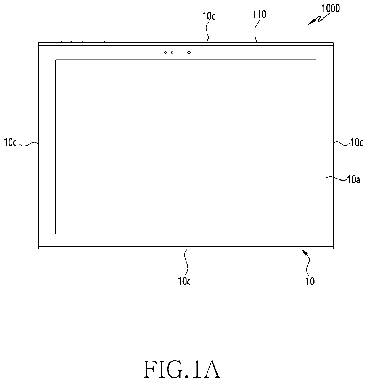
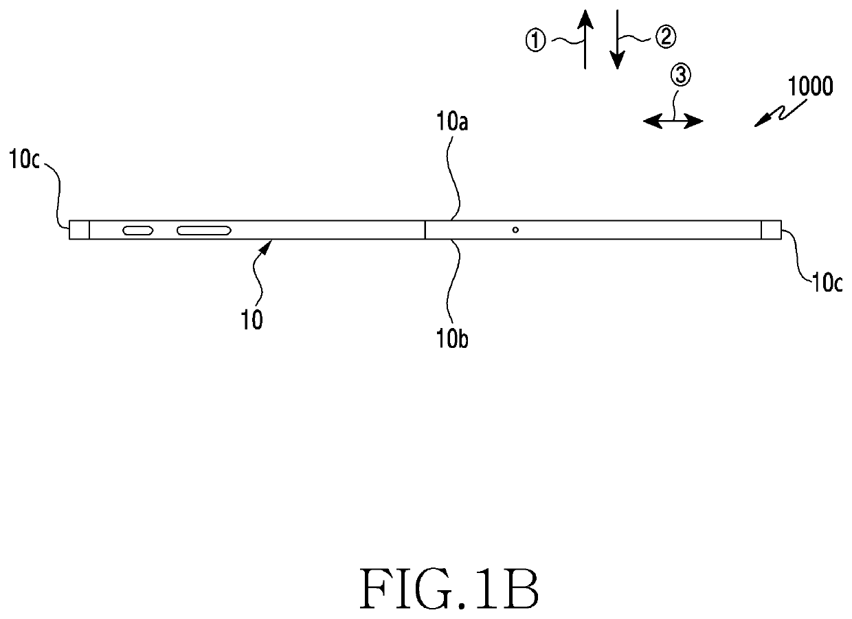
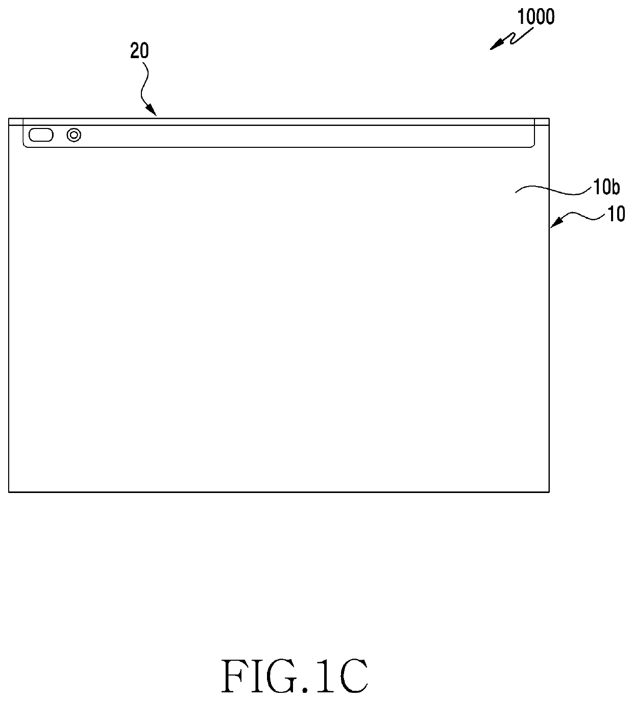
[0053]FIG. 1A is a plan view illustrating an electronic device according to various embodiments of the disclosure. FIG. 1B is a side view illustrating an electronic device according to various embodiments of the disclosure. FIG. 1C is a bottom view illustrating an electronic device according to various embodiments of the disclosure.

[0054]Referring to FIG. 1A to FIG. 1C, an electronic device 1000 according to various embodiments of the disclosure may include at least one of, for example, a smartphone, a tablet Perso...


PUM


Abstract

An electronic device according to an embodiment of the disclosure may include a body including a first face which faces a first direction, a second face which faces a second direction opposite to the first direction, and one or more side faces which face a third direction perpendicular to each of the first and second directions, and a rear case which is coupled along the one side faces and includes one or more microphone coupling structures. The rear case may include a rear case outer part, and a rear case inner part coupled to the rear case outer part through horizontal sliding. The microphone coupling structure may include a microphone acoustic duct constructed at the rear case outer part, a microphone rubber mounting portion constructed at the rear case inner part and inserted to the acoustic duct, and a microphone rubber assembled to the microphone rubber mounting portion and spatially coupled to the acoustic duct.

Description

CROSS-REFERENCE TO RELATED APPLICATIONS[0001]This application is a 371 of International Application No. PCT / KR2019 / 012808 filed on Oct. 1, 2019, which claims priority to Korean Patent Application No. 10-2018-0117613 filed on Oct. 2, 2018, the disclosures of which are herein incorporated by reference in their entirety.BACKGROUND1. Field[0002]Various embodiments of the disclosure relate to a microphone coupling structure of an electronic device.2. Description of Related Art[0003]A microphone to be mounted to an electronic device may be configured in a structure in which at least one or more microphones are mounted to an outermost periphery of a body. Such a microphone may be configured in a structure in which an external sound is transferred to the microphone by means of a microphone acoustic duct structure as a sound passage.[0004]A microphone coupling structure including the microphone acoustic duct may be a one-piece structure or a two-piece structure. In case of the one-piece micr...

Claims


Application Information

Patent Timeline
Patent Type & Authority Applications(United States)
IPC IPC(8): H04R1/08H04R1/28H04R1/34
CPCH04R1/08H04R2499/11H04R1/342H04R1/2876H04R1/021H04R1/2823H05K5/0086H05K5/03
Inventor KIM, SEONGHYEONPARK, JUNGBAEKANG, HYOSUNGSEO, HYOWONSUNG, HAEWON
Owner SAMSUNG ELECTRONICS CO LTD
Why Eureka
Try Eureka