
Heat sink retaining device

a technology of retaining device and heat sink, which is applied in the direction of semiconductor/solid-state device details, cooling/ventilation/heating modification, semiconductor devices, etc., can solve the problems of poor stability, easy damage of heat sink fins, and non-ignorable problems, and achieves easy damage and poor stability.

Inactive Publication Date: 2008-04-17
INVENTEC CORP
View PDF13 Cites 0 Cited by
  • Summary
  • Abstract
  • Description
  • Claims
  • Application Information

AI Technical Summary

Benefits of technology

[0007]In view of the problems of the above conventional art, the present invention provides a heat sink retaining device, which is used for settling the conventional problems of being easily damaged and the poor stability, reliability and fastness when an elastic member or adhering manner is adopted to fix and position the heat sink on the chip, and also for overcoming the disadvantages concerning being inconvenient in assembling and disassembling of the conventional heat sink retaining devices.
[0012]1. In the heat sink retaining device of the present invention, by the manner of pivotally rotating the rotating component to snap onto the chip unit thus making the retaining component press the heat sink against the chip unit, i.e. without an assembling / disassembling tool and forming holes for retaining, the heat sink is easily assembled / disassembled on the chip unit, so as to achieve the goal of being convenient in assembling / disassembling.
[0013]2. In the heat sink retaining device of the present invention, by the manner of pivotally rotating the rotating component to snap onto the retaining component by the elastic force provided by a reed thus making the retaining component press the heat sink against the chip unit by a uniformly distributed directly downward pressing force, the stability of the combination thereof is improved.

Problems solved by technology

However, a following problem of the high chip temperature and the heat dissipation measures has become a non-ignorable problem or even a problem urgently calling for an effective solution.
However, as for the conventional positioning manner for locking the heat sink, holes must be formed on the surface of the chip for snapping a fastener, or other tools are required when locking with a screw, and spin-locking the screw will easily cause a damage of the heat sink fins.
Moreover, the manner of snapping a fastener or an elastic member to a substrate not only has disadvantages concerning poor stability and being easy to be damaged, but also has defects concerning failure on improving the snapping effect as the elastic force is not a directly downward pressing snapping force, the non-uniform force and being difficult in disassembling.
In order to solve the above problems, an adhering manner is provided in the conventional art to mount and fix the above heat sink on the CPU or chip, however, a chemical change tends to occur in the adhesive used in the adhering manner on the junction surface, which causes many uncertainties for the fastness of the adhering, the reliability of a long time adhering is low, and the stability of the adhesive for adhering can not be ensured directly, so that all of the above problems are the troubles and defects caused by the conventional heat sink retaining devices.
Therefore, in the conventional heat sink retaining device, if an elastic component is adopted to mount and fix the heat sink on the surface of the CPU or the chip, it has the disadvantage of damaging the heat sink and the stability and being inconvenient in assembling and disassembling, or if the adhering manner is adopted, it has the problems concerning the reliability and fastness.

Method used


Image

  • Heat sink retaining device
  • Heat sink retaining device
  • Heat sink retaining device

Examples


Embodiment Construction

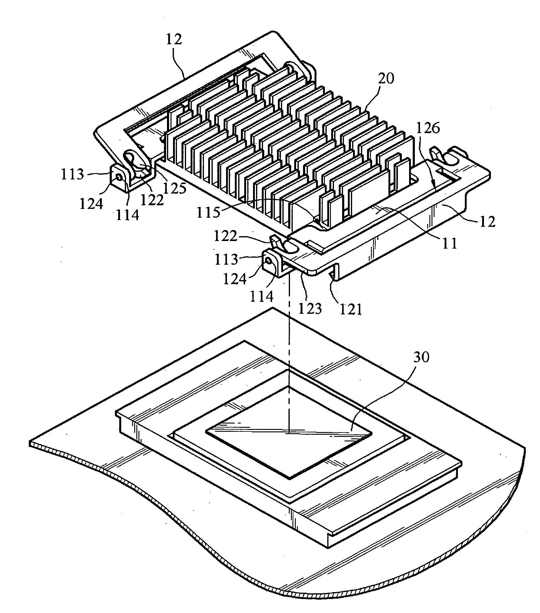
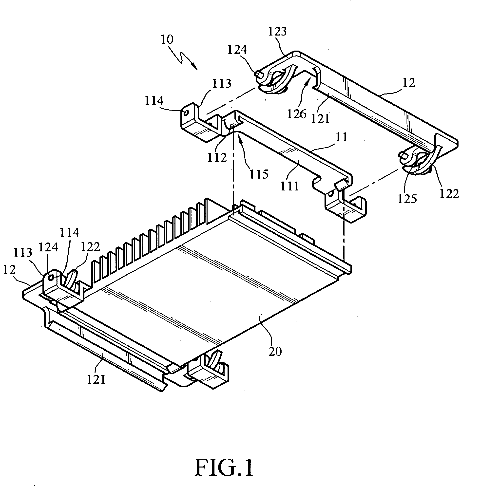
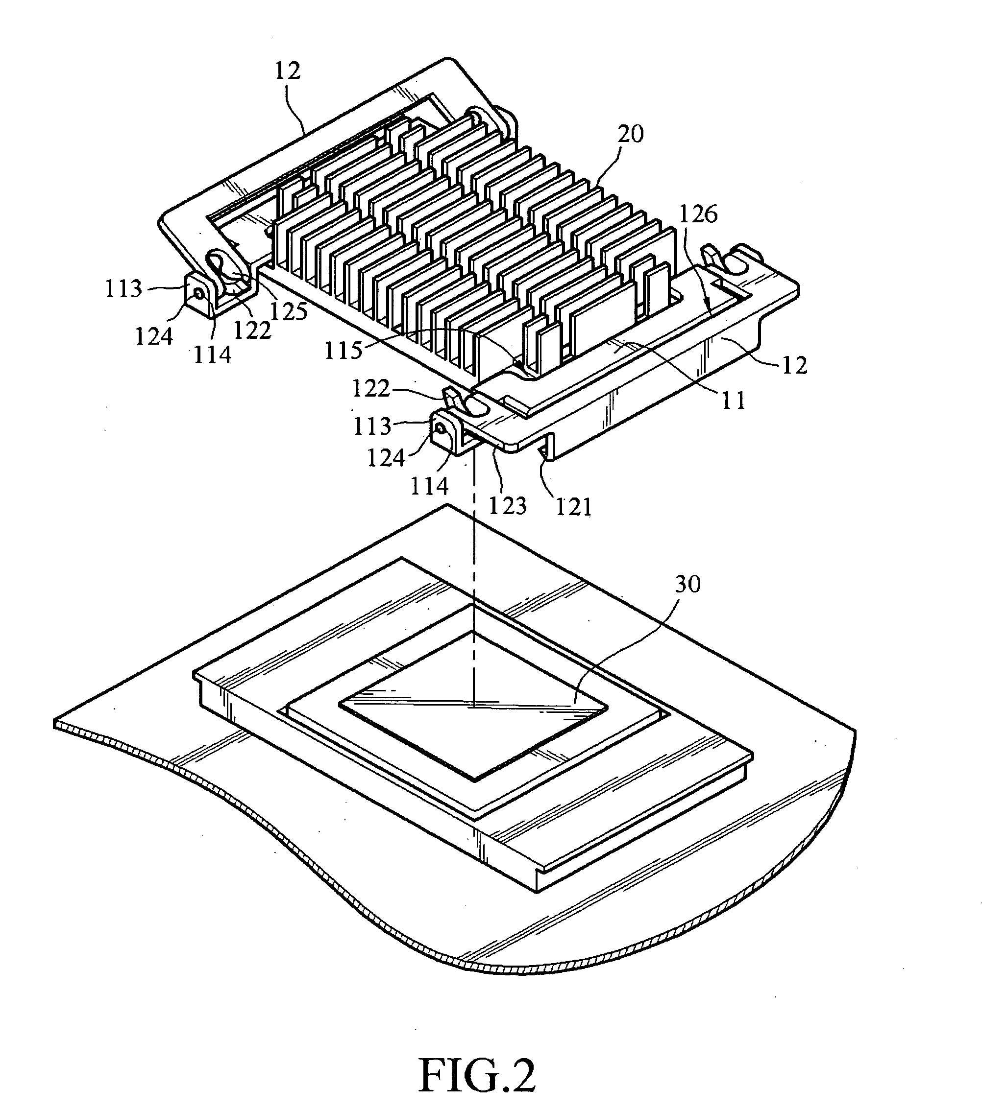
[0021]Please refer to FIGS. 1 and 3. FIG. 1 is a combined schematic view of a heat sink retaining device 10 according to the present invention. FIG. 3 is a schematic view of a snapping and release state of the heat sink retaining device 10 according to the present invention. As shown in FIGS. 1 and 3, the heat sink retaining device 10 for attaching a heat sink 20 on a chip unit 30 includes a retaining component 11 and a rotating component 12. The retaining component 11 has a pressing portion 111 for pressing against the heat sink 20 and a hook portion 112 for being locked to the heat sink 20. The rotating component 12 has a clamping portion 121 and is pivotally disposed on the retaining component 11 and pivotally rotated between a locking position M1 and a release position M2. When the rotating component 12 is at the locking position M1, the clamping portion 121 is snapped onto the chip unit 30, so as to press the pressing portion 111 against the heat sink 20 and the chip unit 30.

[0...


PUM


Abstract

A heat sink retaining device for attaching a heat sink on a chip unit is provided, which includes a retaining component and a rotating component. The retaining component is locked to the heat sink in a state of pressing by a hook portion thereof, and the rotating component is pivotally disposed on the retaining component and pivotally rotated between a release position and a locking position. When the rotating component is at the locking position, a clamping portion of the rotating component is snapped onto the chip unit and presses the retaining component against the heat sink and the chip unit, thus improving the stability, reliability and fastness of the integral combination and meanwhile achieving the goal of being extremely convenient in assembling or disassembling.

Description

BACKGROUND OF THE INVENTION[0001]1. Field of the Invention[0002]The present invention relates to a retaining device, and more particularly, to a heat sink retaining device for attaching a heat sink on a chip unit.[0003]2. Related Art[0004]The booming development of the software and hardware pushes computers and the peripherals thereof to continuously improve in speed and quality. However, a following problem of the high chip temperature and the heat dissipation measures has become a non-ignorable problem or even a problem urgently calling for an effective solution. Therefore, in order to effectively reduce the operating temperature of the CPU or the chip on the motherboard of a computer, most of the designers dispose a group of heat sinks with preferred heat dissipation effect on the CPU or on the chip. The most common ones are, for example, a heat sink formed by aluminum extruded heat sink fins, or a heat sink comprising heat conducting piping, or a heat sink formed by aluminum ext...

Claims


Application Information

Patent Timeline
IPC IPC(8): H05K7/20
CPCH01L23/4093H01L2924/0002H01L2924/00
Inventor CHEN, WIN-HAW
Owner INVENTEC CORP
Learn More