Antenna package and image display device including the same

a technology of image display device and antenna package, which is applied in the direction of individual energised antenna array, loop antenna with ferromagnetic core, antenna earthing, etc., can solve the problems of power loss and signal loss of the antenna, signal noise may also be generated, and circuit wiring and bonding failures of the antenna, etc., to improve the productivity of the antenna package, reduce the length or an area of the circuit board having a relatively thick or multi-layered structure, and increase the length of the transmission region

Active Publication Date: 2022-06-16
DONGWOO FINE CHEM CO LTD
View PDF3 Cites 0 Cited by
  • Summary
  • Abstract
  • Description
  • Claims
  • Application Information

AI Technical Summary

Benefits of technology

[0026]According to embodiments of the present invention, a length of a transmission line included in an antenna device may be formed to be greater than or equal to a length of a signal wiring included in a circuit board. Accordingly, a length or an area of the circuit board having a relatively thick or multi-layered structure may be reduced, thereby improving productivity of the antenna package.
[0027]In some embodiments, a length of a transmission region of the antenna device may be increased, so that the antenna device may be bent through the tra...

Problems solved by technology

In this case, damages to circuit wirings and bonding failures with the antenna due to a bending stress may be caused.
Additionally, power loss and signal loss to the antenna may occur due to the circuit board, and signal noises may also be generated due to the circuit board.
Further, as a thickness of the image d...

Method used


Image

  • Antenna package and image display device including the same
  • Antenna package and image display device including the same
  • Antenna package and image display device including the same

Examples


example

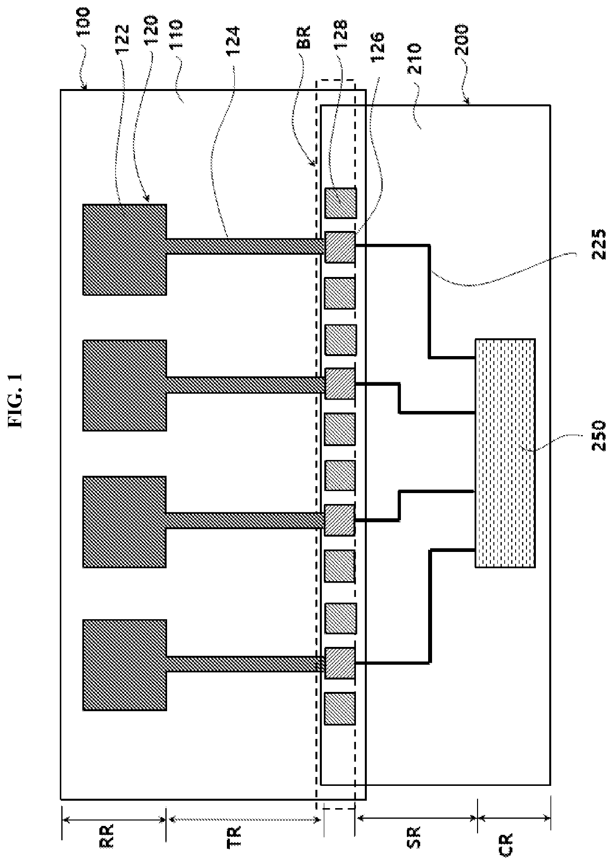
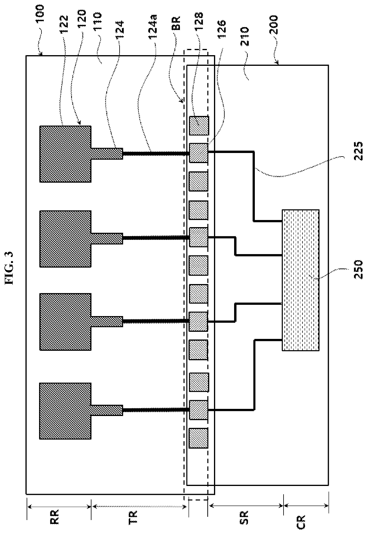
[0112]An antenna unit was formed using an APC alloy on a COP dielectric layer. Specifically, a size of the radiator was 2.8 mm×2.8 mm, and a size of a transmission line was 1.0 mm (width)×10 mm (length), and two antenna units were arranged on the dielectric layer.

[0113]A flexible printed circuit board (FPCB) (total thickness: 500 μm) including circuit wirings on an LCP core layer was prepared. A length of a bonding region of the FPCB was adjusted to be 1 mm, a length of the signal transmission region was 8 mm, and a length of the connector region to be 5 mm.

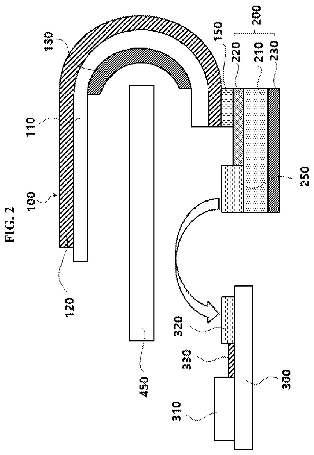
[0114]The FPCB was connected to the transmission lines of the antenna units through the bonding region of the FPCB, and a portion of the COP dielectric layer portion where the transmission lines were arranged was bent downwardly to connect the connector included in the FPCB to a main board.

experimental example

[0116]A feeding was performed to the antenna units included in each antenna package of Example and Comparative Example, and S-parameter (S11) and antenna gain were measured at 28 GHz using a network analyzer and a mmWave measuring instrument (C&G Microwave).

[0117]The evaluation results are shown in Table 1 below.

TABLE 1S11 (dB)Antenna Gain (dBi)Example−8.14.6Comparative Example−8.24.0

[0118]Referring to Table 1, in Example where the length of the transmission region of the antenna device was increased and the transmission region was bent for the feeding and connection with the driving integrated circuit chip, improved antenna radiation properties were achieved.


PUM


Abstract

An antenna package according to an embodiment of the present disclosure includes an antenna device including a dielectric layer and an antenna unit disposed on the dielectric layer, and a circuit board. The antenna unit includes a radiator and a transmission line extending from the radiator. The circuit board includes a core layer and a signal wiring disposed on the core layer and electrically connected to the antenna unit. The circuit board has a bonding region adhered to the antenna device, a signal transmission region including the signal wiring and a connect region including a connector connected to a terminal end portion of the signal wiring. A length of the transmission line of the antenna unit is greater than or equal to a length of the signal transmission region of the circuit board.

Description

CROSS-REFERENCE TO RELATED APPLICATION AND CLAIM OF PRIORITY[0001]This application claims priority to Korean Patent Application No. 10-2020-0173089 filed on Dec. 11, 2020 in the Korean Intellectual Property Office (KIPO), the entire disclosures of which are incorporated by reference herein.BACKGROUND1. Field[0002]The present invention relates to an antenna package and an image display device including the same. More particularly, the present invention relates to an antenna package including an antenna device and a circuit board and an image display device including the same.2. Description of the Related Art[0003]As information technologies have been developed, a wireless communication technology such as Wi-Fi, Bluetooth, etc., is combined with an image display device in, e.g., a smartphone form. In this case, an antenna may be combined with the image display device to provide a communication function.[0004]According to developments of a mobile communication technology, an antenna ca...

Claims


Application Information

Patent Timeline
IPC IPC(8): H01Q1/24H01Q1/38H01Q1/48
CPCH01Q1/243H01Q1/2283H01Q1/48H01Q1/38H01Q1/50H01Q1/24H01Q21/00H01Q1/44H01Q1/2291H01Q21/08H01Q7/06
Inventor KIM, NA YEONSHIN, SEUNG HYUN
Owner DONGWOO FINE CHEM CO LTD
Why Eureka
Try Eureka