Communications cable interconnection apparatus and associated method for an open office architecture

a communication cable and open office technology, applied in the direction of dressing tables, cabinets, walls, etc., can solve the problems of large amount of cable required, large amount of wiring or other cables required, and little or no security from interference therewith, so as to reduce the amount of wiring or other cables, eliminate general access, and eliminate the need for centralized idfs

Inactive Publication Date: 2000-09-05
FABTING TECH
View PDF23 Cites 25 Cited by
  • Summary
  • Abstract
  • Description
  • Claims
  • Application Information

AI Technical Summary

Benefits of technology

In view of the foregoing background, it is therefore an object of this invention to provide a system and method for decentralizing cable termination and switching to smaller user-defined zones located in close proximity to the work stations served. Such will thereby eliminate or diminish the need for centralized IDFs, decrease the amount of wiring or other cable required for each work station, and provide security by isolating user systems and eliminating general access by others. Further, rentable floor space will be made available by utilizing plenum space between a true ceiling and a suspended false ceiling of tiles, or between a false floor and a structural floor. The objects of this invention ar

Problems solved by technology

Each work station with communications capability added or changed requires new lengths of cable to be led to and from the centralized IDF, often involving lengthy and circuitous routing, thus extensive amounts of cable are required.
Another disadvantage of I

Method used


Image

  • Communications cable interconnection apparatus and associated method for an open office architecture
  • Communications cable interconnection apparatus and associated method for an open office architecture
  • Communications cable interconnection apparatus and associated method for an open office architecture

Examples


Embodiment Construction

The present invention will now be described more fully hereinafter with reference to the accompanying drawings, in which preferred embodiments of the invention are shown. This invention may, however, be embodied in many different forms and should not be construed as limited to the embodiments set forth herein. Rather, these embodiments are provided so that this disclosure will be thorough and complete, and will fully convey the scope of the invention to those skilled in the art. Like numbers refer to like elements throughout.

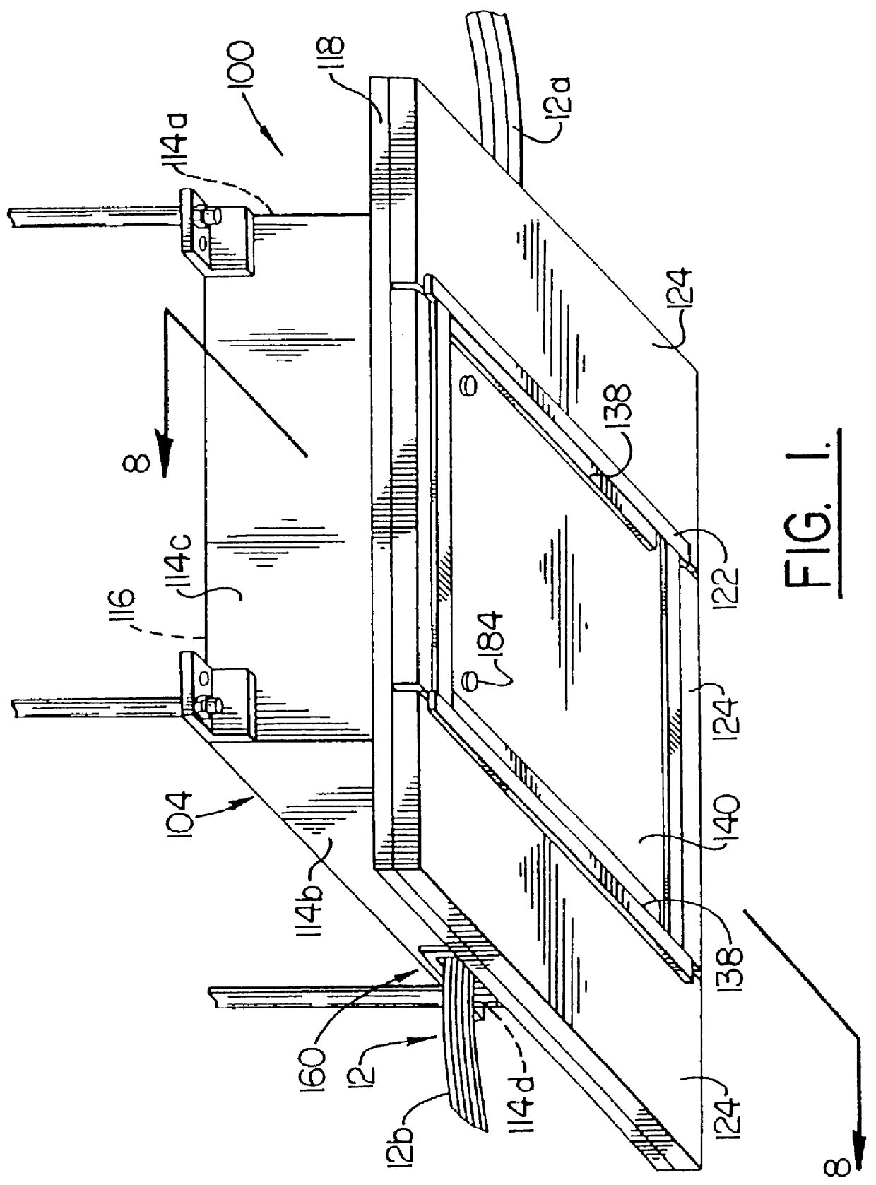
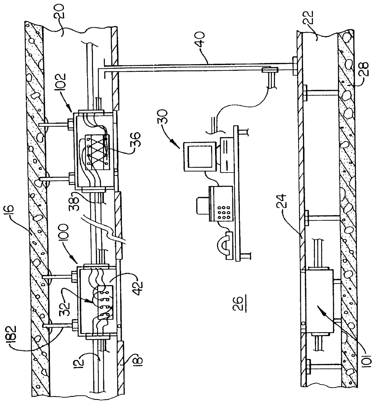
Referring initially to FIG. 1, a cabling termination cabinet 100 for interconnection of communications cables 12 useful with work stations 14 in an open office architecture, as illustrated with reference to FIG. 2. By way of example, the cabinet 100 is adapted for installation between a horizontally extending, generally planar support structure, such as a support ceiling 16 and a generally planar partition, such as a drop ceiling 18, vertically spaced from the s...


PUM


Abstract

Communications cable is routed within horizontal pathways between the structural ceiling and drop ceiling to a fire-resistant cabinet mounted between the ceilings. Communication cable switching and termination equipment is carried by the cabinet for providing a consolidation point and cross-connect location for both copper wire and optical fiber cables serving work stations within an open office architecture. The cabinet includes an access door opening into a room below the drop ceiling for providing user access to the equipment. The door lies within the drop ceiling plane when in the closed position. A removable equipment mounting plate is carried by the cabinet for lowering the equipment below the drop ceiling when the door is in the open position. Cabinet fire-resistant side wall penetrations permits the communications cable routed between the ceilings to enter and exit the cabinet for connection with the communications cable switching and termination equipment. With the use of the cabinet, the amount of communication cable required to service work stations in an open office architecture is greatly reduced.

Description

BACKGROUND OF INVENTION1. Field of InventionThe present invention relates generally to the routing and distribution of low voltage cabling within a building, and more particularly to the routing of communications cable, including voice, data, and video to a consolidation point through horizontal cable runs for user access to the cable proximate user work stations.2. Description of Background ArtThe concept of an open office and open office architecture has become accepted practice in many businesses and in many countries. Open office architecture permits communication cable to be routed from its entry into a building through risers vertically to wiring closets on multiple floors, horizontally to a distribution point within a work area, and ultimately to user work stations.Heretofore in the telecommunications industry, in order to provide telephone or networking service to a plurality of customers in a building, a centralized location has been designated which is customarily called a...

Claims


Application Information

Patent Timeline
IPC IPC(8): H02G3/18E04B9/02E04F19/08E04C2/52H02G3/00H02G3/38
CPCH02G3/00H02G3/185H02G3/281
Inventor MURRAY, RICHARD A.MURRAY, VICTOR E.
Owner FABTING TECH
Why Eureka
Try Eureka