

Fuel dilution methods and apparatus for NOx reduction
Inactive Publication Date: 2002-05-07
JOHN ZINK CO LLC
View PDF55 Cites 96 Cited by
- Summary
- Abstract
- Description
- Claims
- Application Information
AI Technical Summary
Benefits of technology
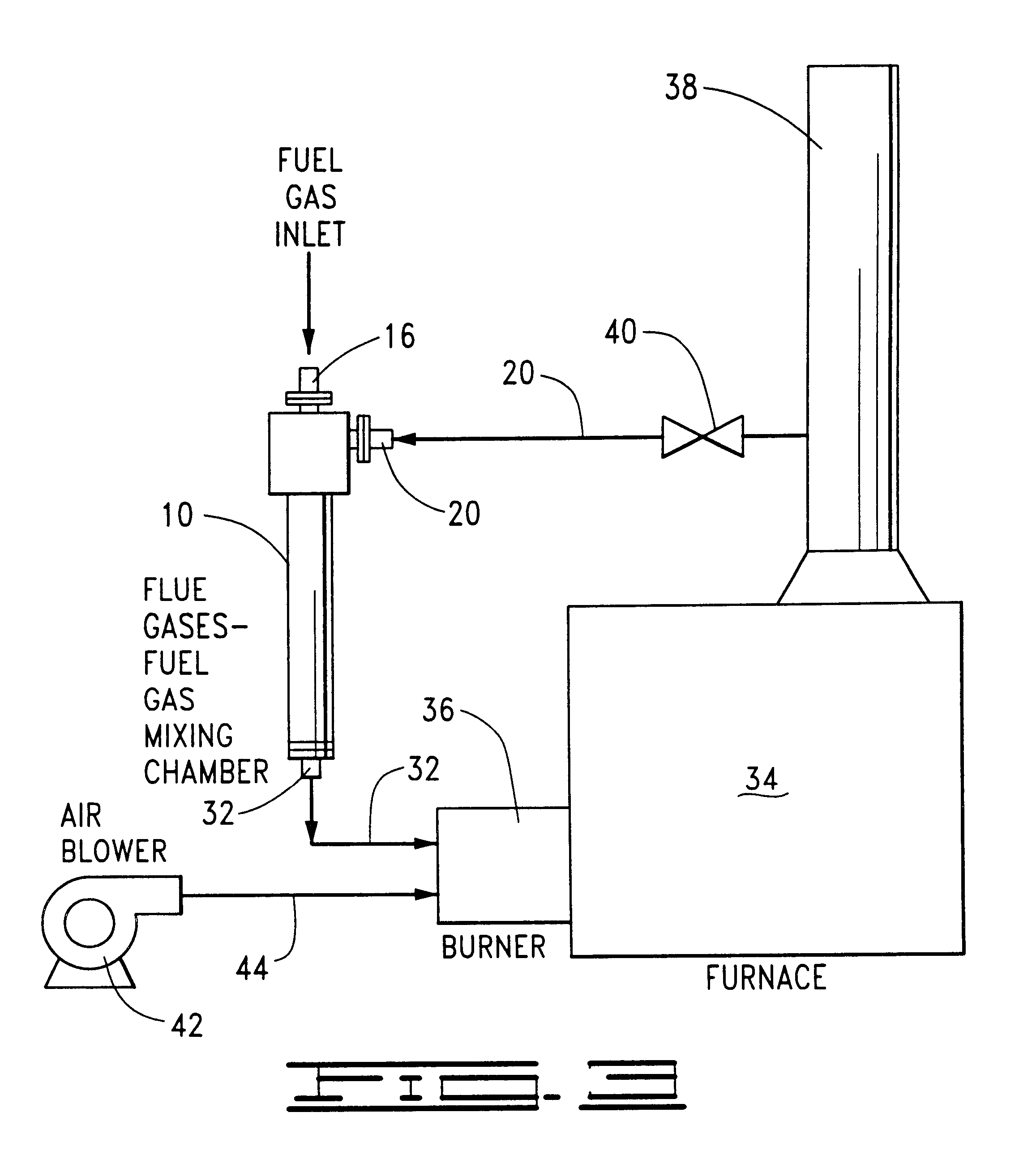
The apparatus of this invention can be integrated into an existing burner-furnace system without substantially modifying or replacing existing burners, air blowers and the like and reduces the content of nitrogen oxides in the flue gases produced by the combustion of fuel gas and combustion air in the furnace. At most, the burners may require minor modifications to accommodate the increased mass and reduced pressure of the flue gases-fuel gas mixture, e.g., the replacement of the burner tips.
Problems solved by technology
Nitrogen oxide emissions are associated with a number of environmental problems including smog formation, acid rain and the like.
While the above described techniques for reducing NO.sub.x emissions with flue gas have been effective in reducing NO.sub.x formation and flue gas NO.sub.x content, there are certain disadvantages and drawbacks associated with them.
The modifications often result in increased flame spread and other combustion zone changes which require internal alterations to the furnaces in which modified burners are installed.
The changes and modifications required often involve substantial capital expenditures, and the modified furnaces and burners are often more difficult and costly to operate and maintain than those they replaced.
Method used
View moreImage
Smart ImageViewing Examples

Examples
example
The apparatus illustrated in FIG. 5 was tested to determine the nitrogen oxides content of the flue gases at various ratios of flue gases mixed with the fuel gas, various ratios of flue gases mixed with the combustion air and a combination of the two. The furnace utilized in the test was a 63.5 million BTU steam generator. The results of these tests are given in the Table below.
From the above Table, it can be seen that the methods and apparatus of the present invention produce flue gases having unexpected reduced nitrogen oxides content.
Login to View More PUM
| Property | Measurement | Unit |
|---|---|---|
| Content | aaaaa | aaaaa |
| Volume ratio | aaaaa | aaaaa |
| Combustion | aaaaa | aaaaa |
Abstract
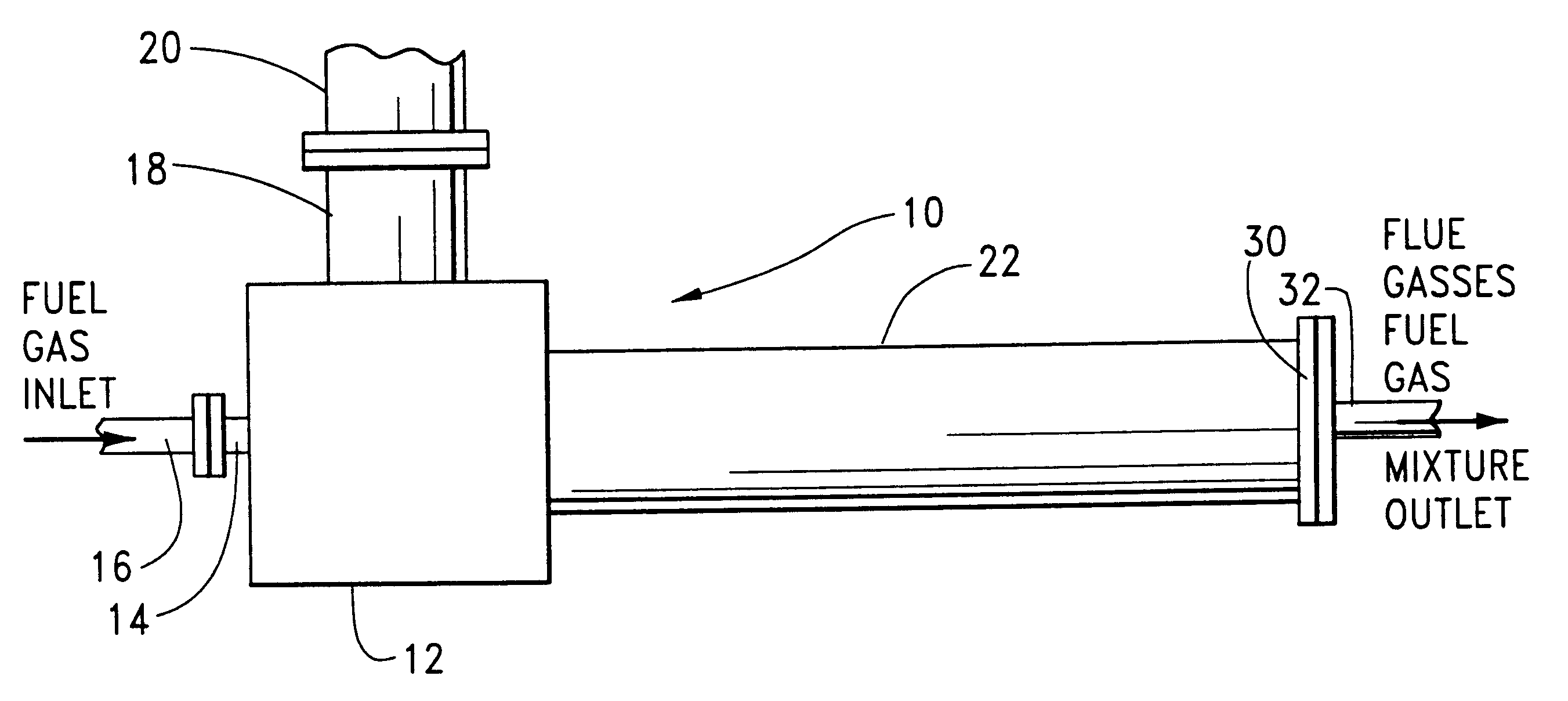
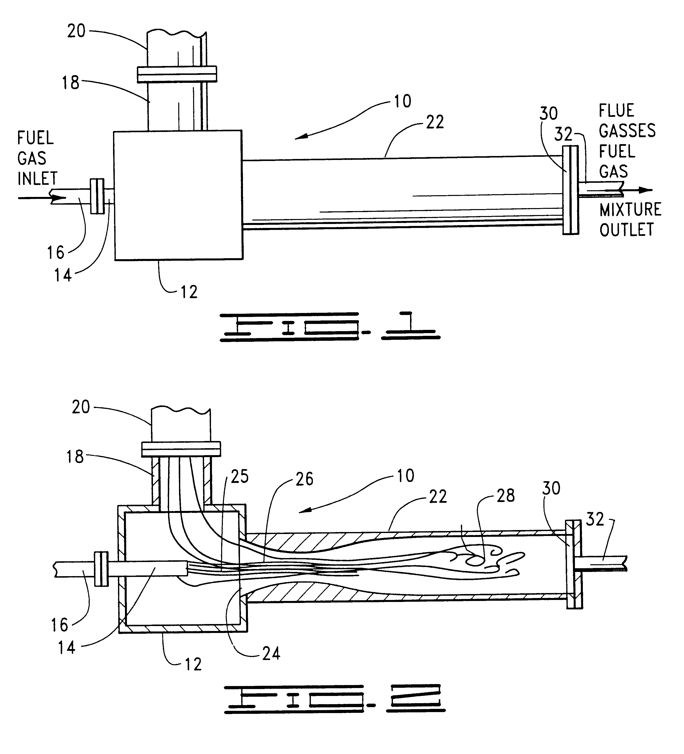
Methods and apparatus for reducing the content of nitrogen oxides in the flue gases produced by the combustion of fuel gas and combustion air introduced into a burner connected to a furnace are provided. The methods basically comprise the steps of conducting the combustion air to the burner, providing a chamber outside of the burner and furnace for mixing flue gases from the furnace with the fuel gas, discharging the fuel gas in the form of a fuel jet into the mixing chamber so that flue gases from the furnace are drawn into the chamber and mixed with and dilute the fuel gas therein and conducting the resulting mixture of flue gases and fuel gas to the burner wherein the mixture is combined with the combustion air and burned in the furnace.
Description
1. Field of the InventionThe present invention relates to fuel dilution methods and apparatus for reducing the production of nitrogen oxides during the combustion of fuel gas and combustion air.2. Description of the Prior ArtNitrogen oxides (NO.sub.x) are produced during the combustion of fuel-air mixtures at high temperatures. An initial, relatively rapid reaction between nitrogen and oxygen occurs predominantly in the combustion zone to produce nitric oxide in accordance with the reaction N.sub.2 +O.sub.2.fwdarw.2NO. The nitric oxide (also referred to as "prompt NO.sub.x ") is further oxidized outside the combustion zone to produce nitrous oxide in accordance with the reaction 2NO+O.sub.2.fwdarw.2NO.sub.2.Nitrogen oxide emissions are associated with a number of environmental problems including smog formation, acid rain and the like. As a result of the adoption of stringent environmental emission standards by government authorities and agencies, methods and apparatus to suppress th...
Claims
Login to View More Application Information
Patent Timeline
 IPC IPC(8): F23C9/00F23C9/08F23L7/00F23C9/06F23C99/00F23D14/48
CPCF23C9/08F23L7/005F23C2202/20F23C2202/30F23L2900/07009F23C2900/09002F23C2202/50F23C9/06
InventorLANG, JERRY M.
OwnerJOHN ZINK CO LLC