Rear projector

a projector and rear-facing technology, applied in the field of rear-facing projectors, can solve the problems of dust etc. flowing outside, weak components of optical devices etc., deteriorating the quality of the image displayed on the screen,

Inactive Publication Date: 2004-10-19
SEIKO EPSON CORP
View PDF11 Cites 23 Cited by
  • Summary
  • Abstract
  • Description
  • Claims
  • Application Information

AI Technical Summary

Benefits of technology

According to the above arrangement, since the discharge pressure of air can be increased, the air inside the large closed space including the interior of the second casing can be securely circulated. This is because the sirocco fan has relatively small opening area on the discharge side as compared to the opening area of the air-drawing side thereof and because the discharge pressure can be increased by discharging the air in a rotary tangential direction.

Problems solved by technology

On the other hand, some of the components of the optical device etc. are weak against heat.
However, when the external air is used to cool the electric optical device, dust etc. flowing outside may sometimes be sucked in together with the air.
When the dust etc. is adhered on an image formation area of the electric optical device, the dust is displayed as shadow on the screen, thereby deteriorating the quality of the image displayed on the screen.
It is possible to provide a filter etc. on the intake opening to prevent dust from being sucked in, improvement in cooling efficiency by increasing the amount of the sucked air often hinders improvement in dust proofness, so that it is difficult to securely prevent the dust while improving the cooling efficiency.

Method used


Image

  • Rear projector
  • Rear projector
  • Rear projector

Examples


Embodiment Construction

)

An embodiment of the present invention will be described below with reference to attached drawings.

[1. Primary Arrangement of Rear Projector]

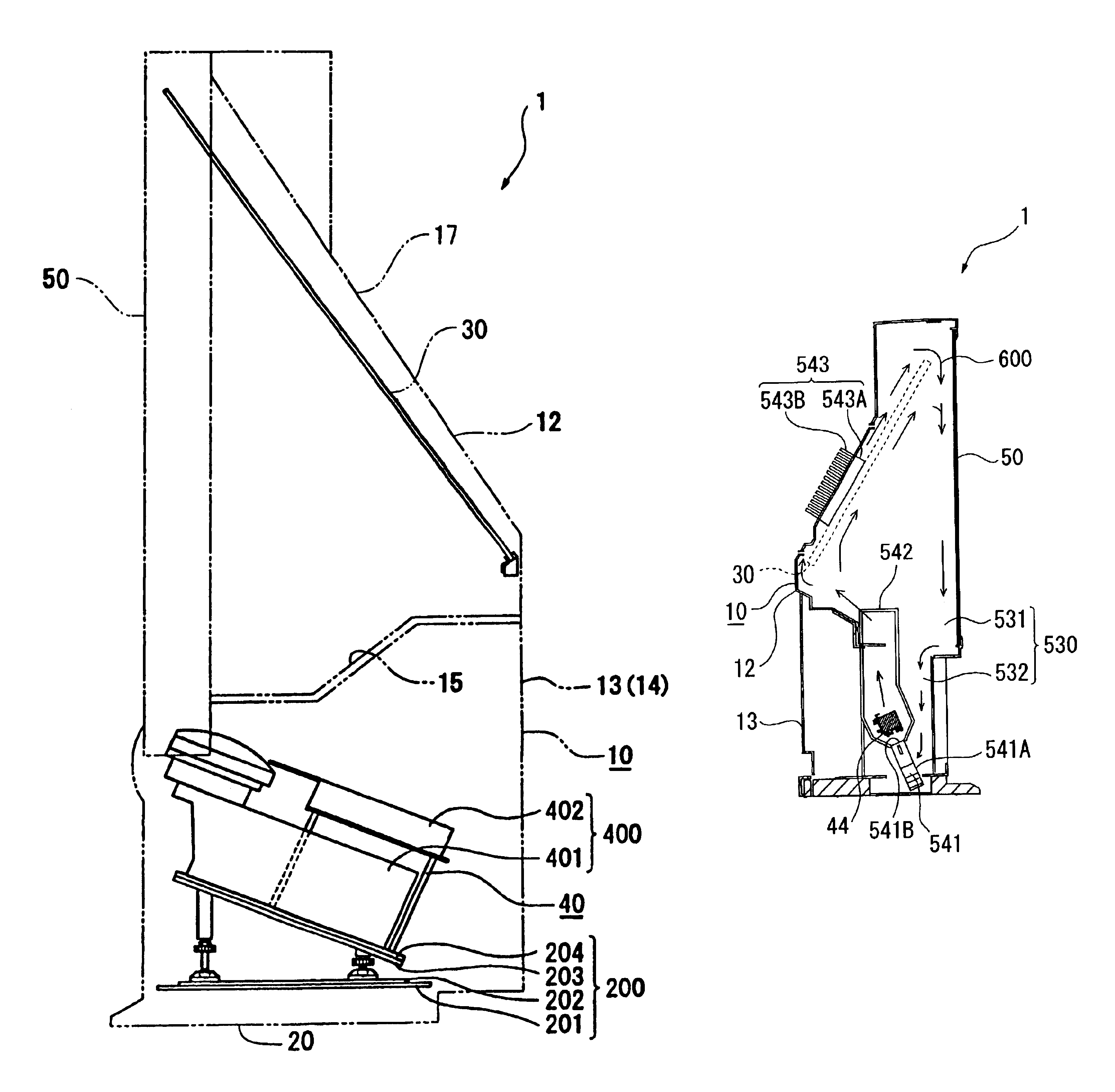
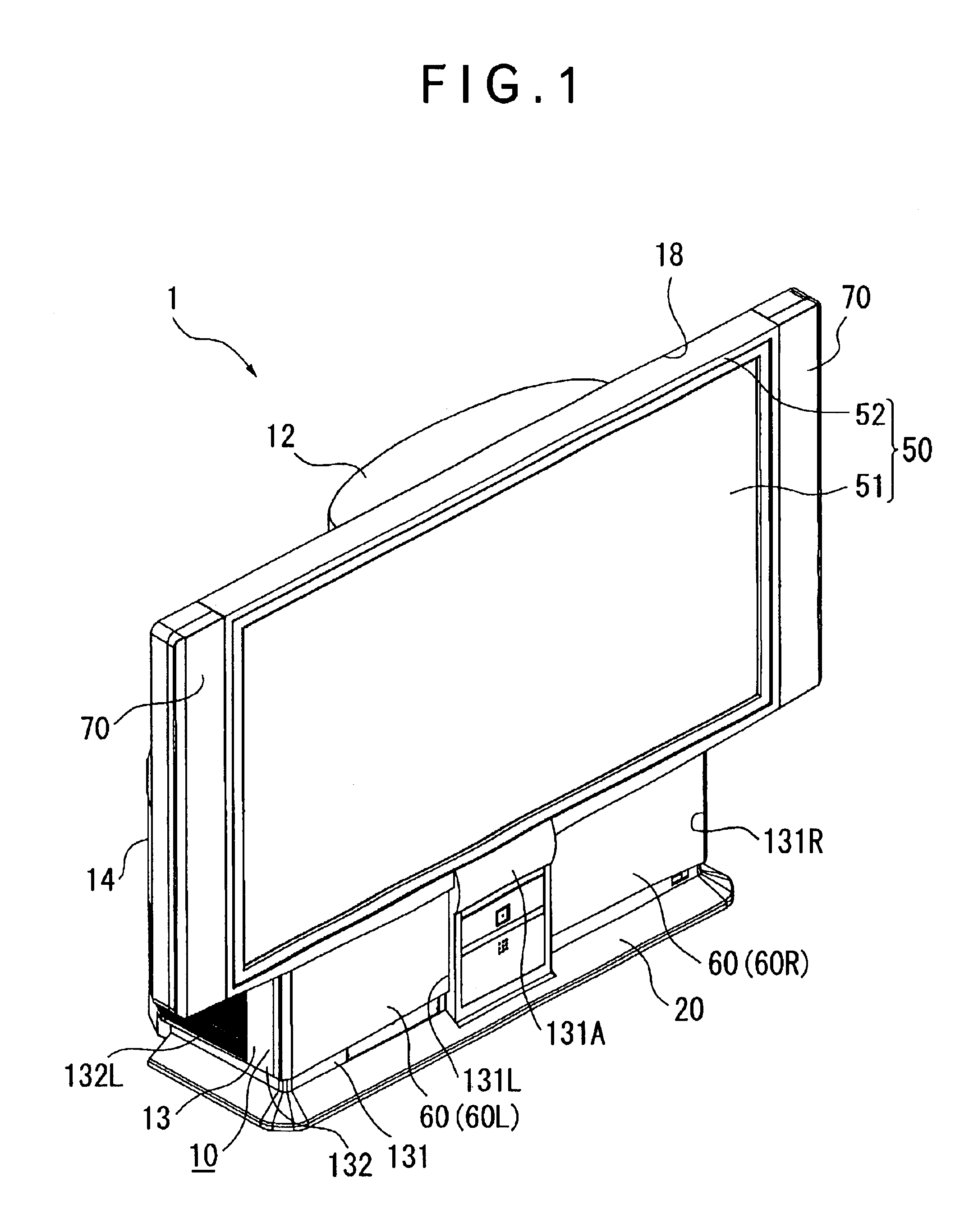
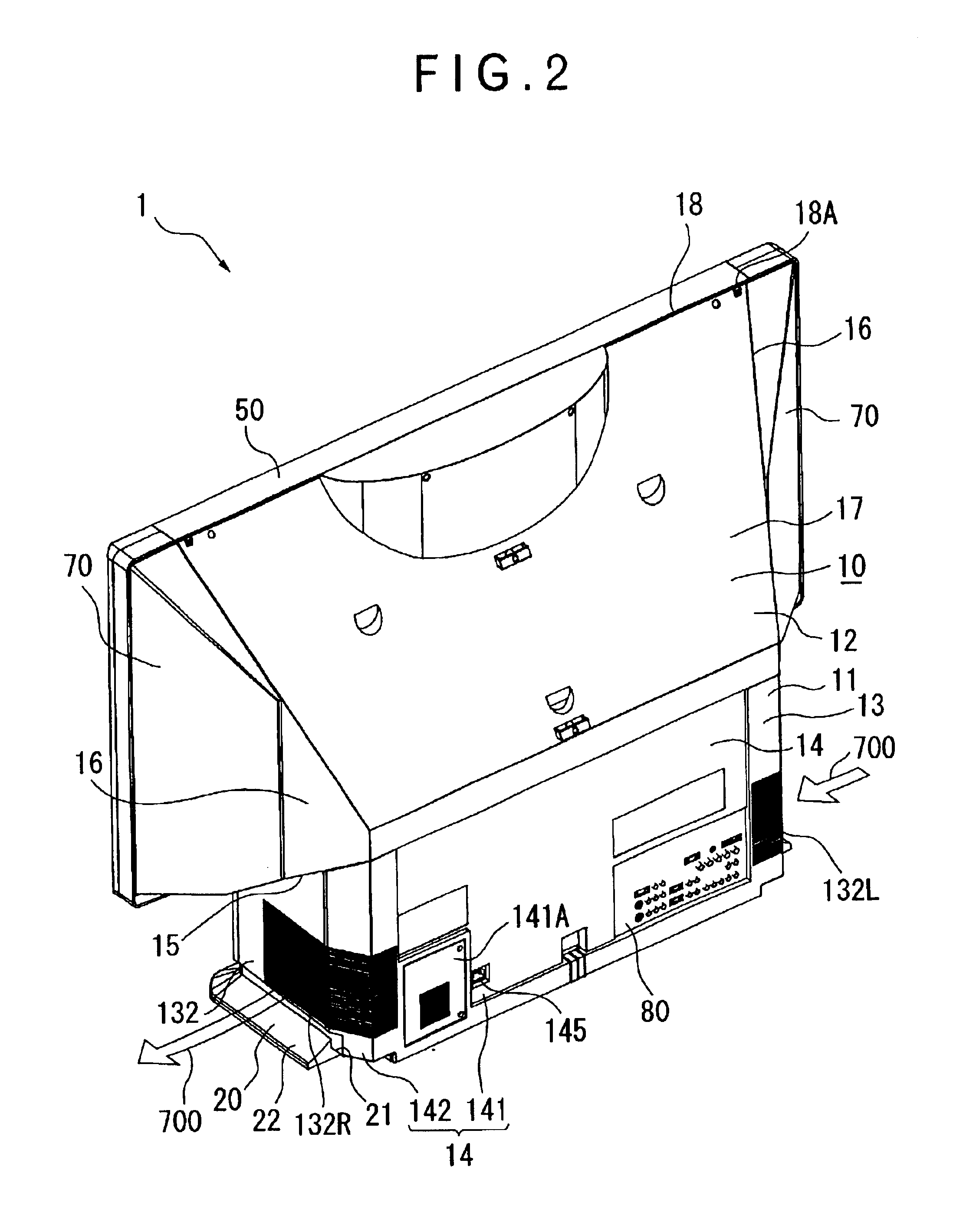
FIG. 1 is a perspective view seen from front side of a rear projector 1 according to an aspect of the present invention. FIG. 2 is a perspective view of the rear projector 1 seen from rear side thereof. FIG. 3 is a vertical cross section schematically showing the rear projector 1.

As shown in FIGS. 1 to 3, the rear projector 1 modulates a light beam irradiated by a light source in accordance with image information to form an optical image, and enlarges and projects the optical image on a screen. The rear projector 1 includes a cabinet 10 constituting a casing, a leg 20 provided on the lower side of the cabinet 10, a reflection mirror 30 located inside the cabinet 10, an interior unit 40 located inside the cabinet 10, and a screen unit 50 exposed on a side of the cabinet 10. The reflection mirror 30 and the interior unit 40 constitute an image g...


PUM

PropertyMeasurementUnit
aspect ratioaaaaaaaaaa
opticalaaaaaaaaaa
heataaaaaaaaaa

Abstract

A rear projector (1) has a closed space (530) including an inside of an upper cabinet (12) and an electric optical device (44), where the electric optical device (44), a sirocco fan (541) located below the electric optical device (44), a duct (542) covering the upper side of the electric optical device (44) and a heat sink (543) attached to the upper cabinet (12) are disposed and an upper cabinet cooling system (600) that cools the interior of the closed space (530) in a circulative manner is provided in the closed space (530), thereby preventing invasion of duct etc. and providing high-quality image.

Description

1. Field of the InventionThe present invention relates to a rear projector having an image generator including an electric optical device for modulating a light beam irradiated by a light source to form an optical image in accordance with image information and a projection optical system for enlarging and projecting the optical image, a casing for disposing the image generator, and a screen exposed on one of the lateral sides of the casing onto which the optical image formed by the image generator is projected2. Description of Related ArtRecently, a rear projector has come to be used in the field of home theater etc. Such rear projector has an image generator for generating a projection image, a box-shaped casing disposing the image generator and a reflection mirror for reflecting the projected image and a transmissive screen exposed to a side of the box-shaped casing.The image generator has a light source lamp, an optical device such as a liquid crystal panel for modulating a light...

Claims


Application Information

Patent Timeline
Patent Type & Authority Patents(United States)
IPC IPC(8): G03B21/10H04N5/74H04N9/31G02F1/1333G03B21/00G03B21/14G03B21/16G02F1/13H04N5/64
CPCG03B21/10H04N9/3141G03B21/16H04N9/3102
Inventor ARAI, JUNYAMADA, HARUYOSHI
Owner SEIKO EPSON CORP
Why Eureka
Try Eureka