Hydraulic control device for working machine

a technology of hydraulic control device and working machine, which is applied in the direction of fluid coupling, servomotor, coupling, etc., can solve the problems of machine stopping completely, affecting the cost and installation of the machine, and the entire amount of oil discharged from the pump being unloaded

Inactive Publication Date: 2005-09-22
KOBELCO CONSTR MASCH CO LTD
View PDF6 Cites 14 Cited by
  • Summary
  • Abstract
  • Description
  • Claims
  • Application Information

AI Technical Summary

Benefits of technology

[0007] An object of the present invention is to provide a hydraulic control device for a working machine which controls a co

Problems solved by technology

Since this passage is provided, each valve is relatively long in a spool-axis direction, and there are disadvantages regarding cost and installation into a machine.
However, if an abnormality (fail) occurs in a control system, for example, if the proportional solenoid valve malfunctions or disconnection occurs in a signal

Method used


Image

  • Hydraulic control device for working machine
  • Hydraulic control device for working machine
  • Hydraulic control device for working machine

Examples


Embodiment Construction

[0015] A hydraulic control device according to an embodiment of the present invention will be described below with reference to FIGS. 1 to 3.

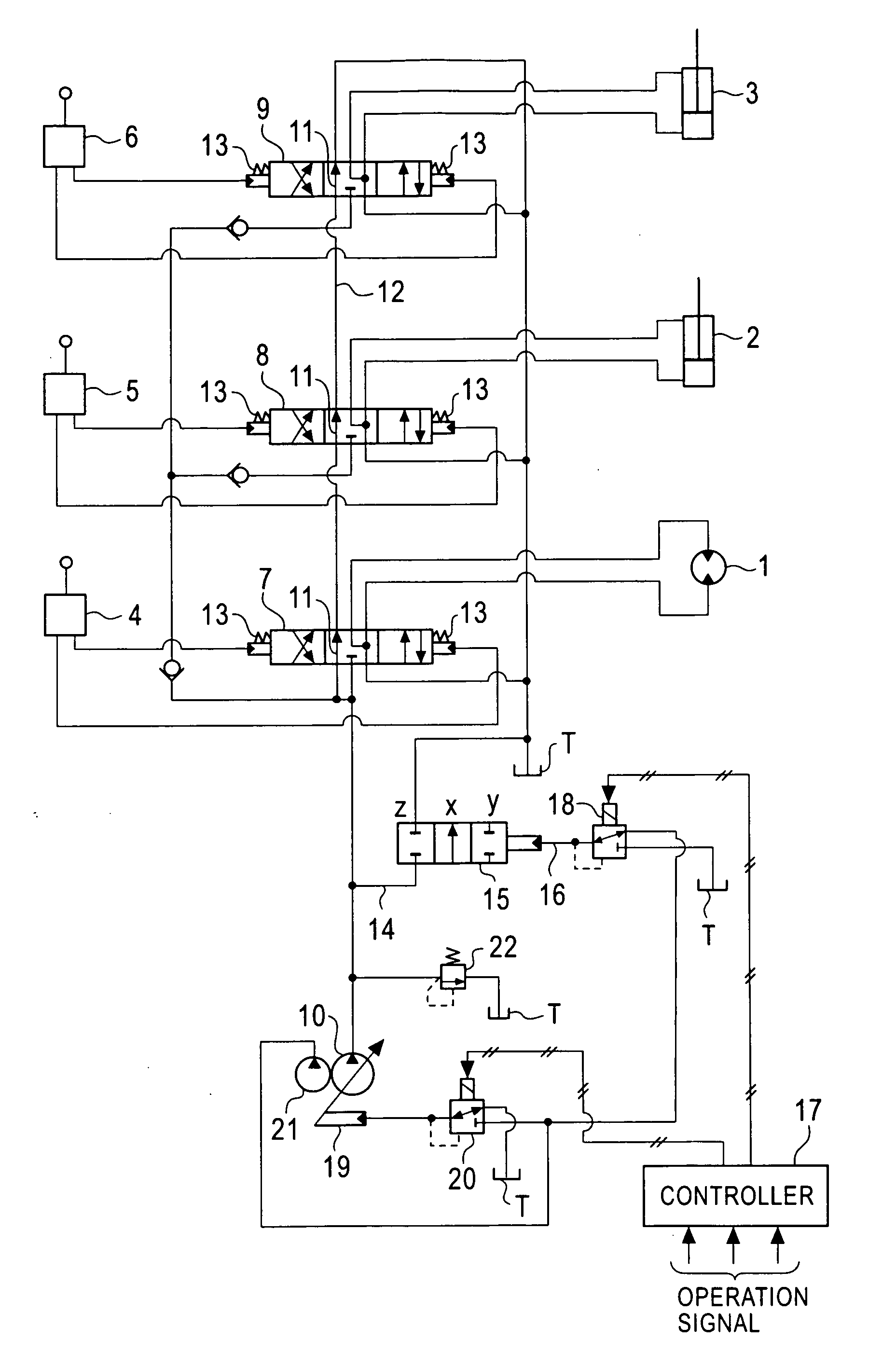
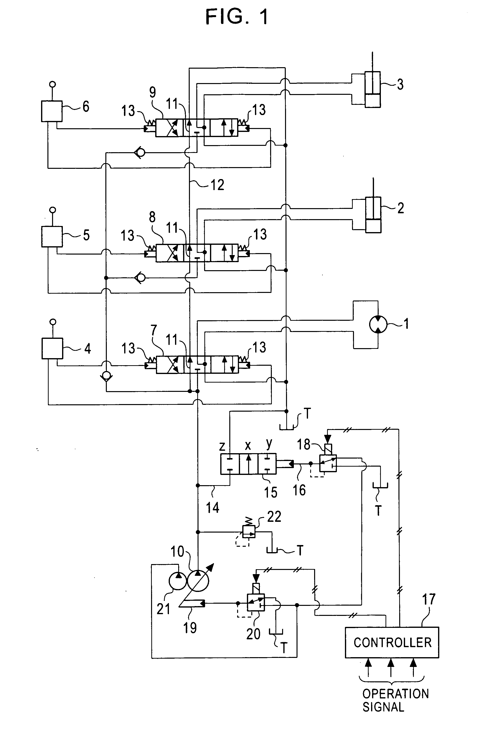
[0016] In this embodiment, a common bleed-off valve is used for bleed-off control of three hydraulic actuators 1, 2, and 3.

[0017] As shown in FIG. 1, the actuators 1, 2, and 3 are connected to a variable displacement (capacity) hydraulic pump 10 via hydraulic pilot control valves 7, 8, and 9 controlled by remote control valves 4, 5, and 6, respectively, which serve as control units.

[0018] The control valves 7 to 9 are connected to the hydraulic pump 10 and a tank T such that they are parallel to each other, and the actuators 1 to 3 are individually controlled by their respective control valves 7 to 9.

[0019] In addition, the control valves 7 to 9 are provided with center bypass passages 11 which function as individual bleed-off passages and open at neutral positions. The center bypass passages 11 are connected to the tank T via a center bypa...


PUM


Abstract

A hydraulic control device for a working machine includes hydraulic actuators, a hydraulic pump which functions as a hydraulic power source, control valves which control the actuators on the basis of operations by an operating unit, a common bleed-off valve which returns excess oil to a tank via an unload passage on the basis of the operations by the operating unit, and a control unit which controls the common bleed-off valve. The common bleed-off valve is capable of setting a position for closing the unload passage when the common bleed-off valve is in a non-operating state. The control valves have center bypass passages which function as individual bleed-off passages which open when the control valves are in neutral states. Opening characteristics of the control valves are set such that the center bypass passages are closed in initial stroke periods in which the control valves move toward operating positions.

Description

BACKGROUND OF THE INVENTION [0001] 1. Field of the Invention [0002] The present invention relates to an hydraulic control device for a working machine, such as a hydraulic excavator. [0003] 2. Description of the Related Art [0004] In a typical hydraulic excavator, bleed-off control is performed in which a part of oil discharged from a pump (excess oil) is returned to a tank. This control is generally performed by varying an opening area of a bleed-off passage provided in a control valve for each actuator depending on a control input of an operating unit. Since this passage is provided, each valve is relatively long in a spool-axis direction, and there are disadvantages regarding cost and installation into a machine. [0005] In addition, a structure in which the above-described passage is omitted and a common bleed-off valve is provided for a plurality of control valves is known. In addition, an electronic control method in which the common bleed-off valve is a hydraulic pilot valve a...

Claims


Application Information

Patent Timeline
IPC IPC(8): E02F9/22F15B11/00F15B11/042F15B20/00
CPCE02F9/2228F15B2211/7741E02F9/226E02F9/2282F15B11/0423F15B20/008F15B2211/20553F15B2211/30525F15B2211/3056F15B2211/3122F15B2211/3127F15B2211/329F15B2211/40515F15B2211/428F15B2211/45F15B2211/50536F15B2211/5151F15B2211/55F15B2211/6652F15B2211/6654F15B2211/7053F15B2211/7058F15B2211/71E02F9/2235F15B2211/41563
Inventor TOJI, YUTAKAOKA, HIDEKAZU
Owner KOBELCO CONSTR MASCH CO LTD
Why Eureka
Try Eureka