X-ray device provided with a robot arm

a robot arm and x-ray technology, applied in the field of x-ray devices, can solve the problems of high cost, insufficient application accuracy, limited flexibility and movement possibilities, etc., and achieve the effect of high positioning accuracy and economic production

Inactive Publication Date: 2005-03-22
U S PHILIPS CORP
View PDF23 Cites 108 Cited by
  • Summary
  • Abstract
  • Description
  • Claims
  • Application Information

AI Technical Summary

Benefits of technology

to provide an as flexible as possible X-ray device which offers a high positioning accuracy and can be manufactured as economically as possible.

Problems solved by technology

It has been found that the solution known from WO 99 / 30614 has the drawback that the flexibility and the possibilities for movement are limited notably because of the mechanical construction.
Granted, the X-ray device known from U.S. Pat. No. 4,894,855 offers a high flexibility, but the accuracy that can be achieved thereby is not adequate for many applications.
Moreover, it requires a plurality of manipulators, each of which must be separately controlled; this leads to high costs and necessitates complex control.
This may lead to a reduction of costs, because the numbers in which C-arm X-ray devices are manufactured are very small, so that the cost of manufacturing the mechanical systems constitutes a significant cost factor.
They continuously measure the distance between the moving parts and the object to be examined and initiate emergency braking as soon as the distance becomes too small and a risk of injury of the object to be examined arises.

Method used


Image

  • X-ray device provided with a robot arm
  • X-ray device provided with a robot arm
  • X-ray device provided with a robot arm

Examples


Embodiment Construction

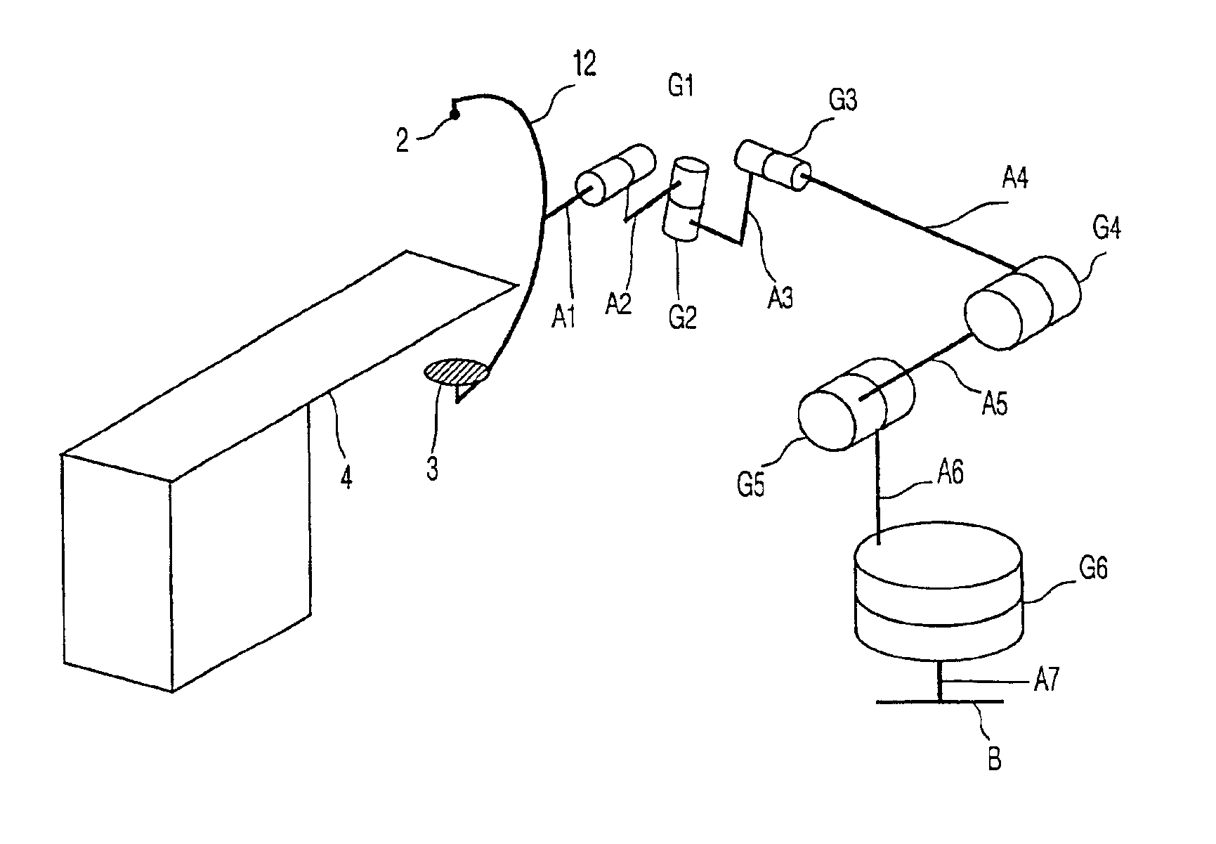
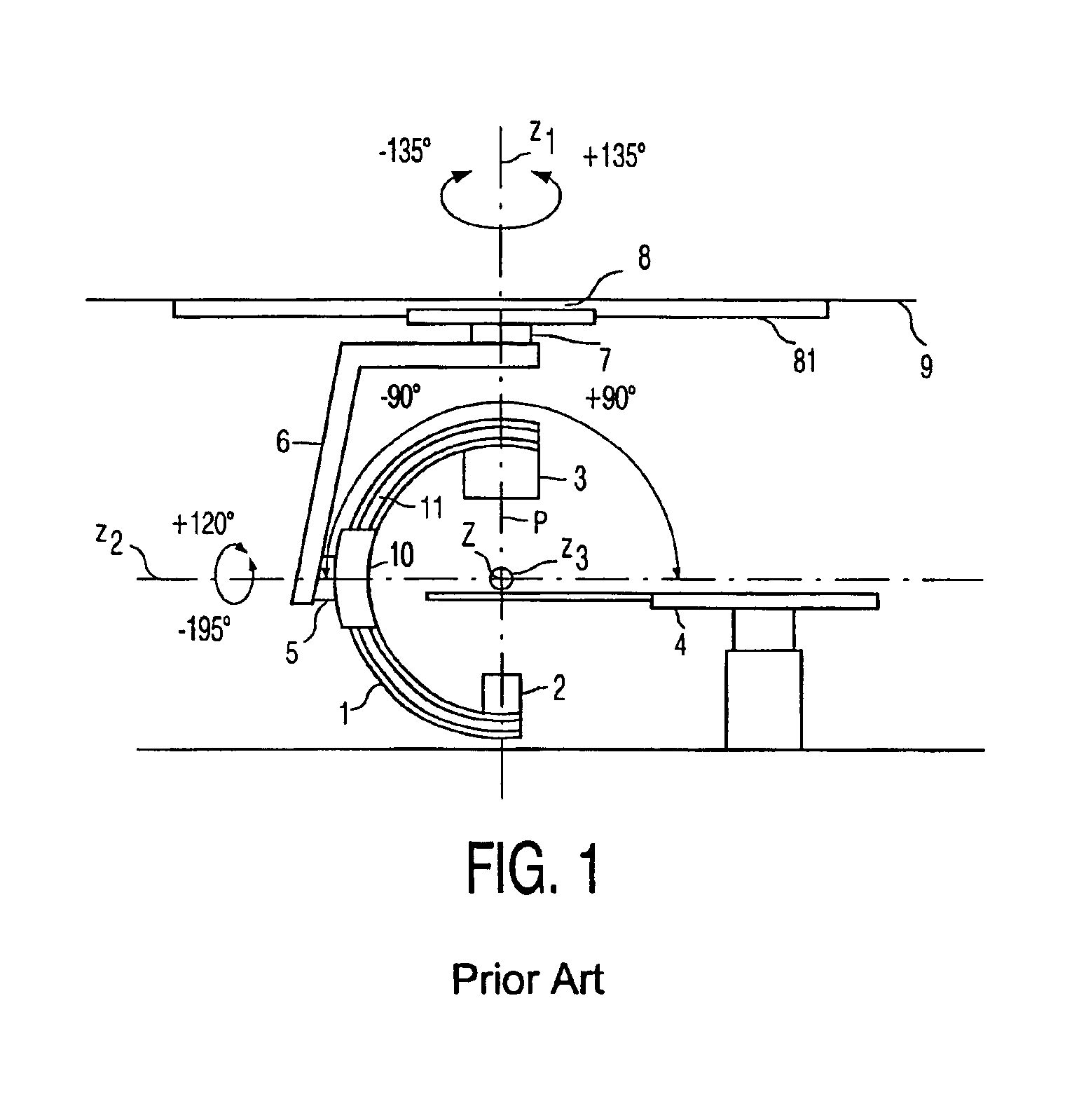
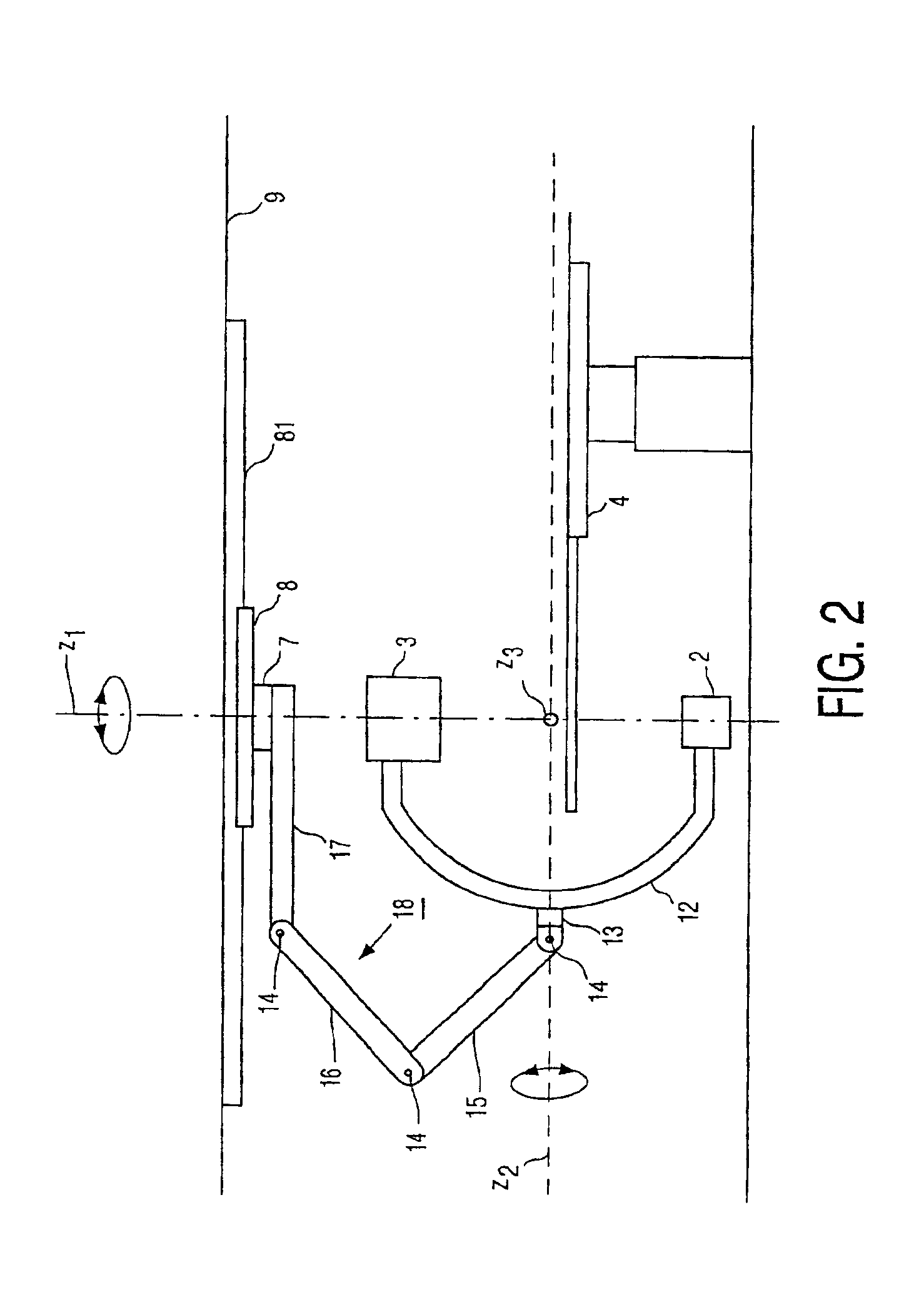
The known X-ray device that is shown in FIG. 1 has a holding device in the form of a C-arm 1 with an X-ray tube 2 and an X-ray detector 3. The tube and the detector are oriented relative to one another in such a manner that X-rays emanating from the X-ray tube 2 along the projection radius P traverse an object to be examined that is arranged on the patient table 4 in the examination zone Z and are incident on the X-ray detector 3. The X-ray tube 2 and the X-ray detector 3 are rotatable about the z3 axis in the given angular range via rails 11 which are provided on the C-arm 1 and extend through a rail holding system 10. The rail holding system 10 is connected to a rigid supporting device 6 via a hinge 5 that allows a rotation of 315° about the z2 axis in the case shown. The latter device itself is mounted, via a hinge 7 which enables rotation about the z1 axis, on a slide 8 which is displaceable in a system of rails 81 which itself is attached to the ceiling 9. As is already indicat...


PUM


Abstract

The invention relates to an X-ray device which includes an X-ray source and an X-ray detector which are mounted at a respective end of a common holding device. The holding device being attached to the room by way of a supporting device. In order to realize a more flexible construction of such X-ray devices that are widely used and are usually provided with a holding device in the form of a C-arm and nevertheless maintain a high positioning accuracy. The invention further relates to a supporting device constructed with a plurality of hinged, serially interconnected supporting members. The supporting device is formed notably by a serial manipulator, for example, a conventional robot arm.

Description

BACKGROUND OF THE INVENTION1. Field of the InventionThe invention relates to an x-ray device provided with an X-ray source and an X-ray detector which are mounted at a respective end of a common holding device, the holding device being connected to the room by way of a supporting device, wherein the supporting device is composed of a plurality of hinged, serially interconnected supporting members.2. Description of the Related ArtFurthermore, WO 99 / 30614 discloses a C-arm X-ray device in which the supporting device is constructed as a parallel manipulator. Therein, a first holding plate that is attached to the C-arm is connected to a second holding plate via a plurality of supporting members; the second holding plate can be attached, for example, to the wall. Each of said supporting members; is connected directly to both holding plates, the points of connection of the supporting members to the holding plates being different. The C-arm can thus be moved to given positions within given...

Claims


Application Information

Patent Timeline
Patent Type & Authority Patents(United States)
IPC IPC(8): A61B6/00B25J9/06A61B6/10
CPCA61B6/4441A61B6/4464A61B6/4452A61B6/4458
Inventor RASCHE, VOLKERSCHOMBERG, HERMANNKLOTZ, ERHARD PAUL ARTUR
Owner U S PHILIPS CORP
Why Eureka
Try Eureka