Component alignment apparatuses and methods

a technology of alignment apparatus and components, applied in the direction of conveyors, final product manufacturing, instruments, etc., can solve the problems of inability to detect the orientation of the body, damage to the component and/or other components connected to the component, and complicated problems,

Inactive Publication Date: 2005-05-24
MICRON TECH INC
View PDF52 Cites 46 Cited by
  • Summary
  • Abstract
  • Description
  • Claims
  • Application Information

AI Technical Summary

Benefits of technology

[0011]The above objectives and others are accomplished by methods and apparatuses in accordance with the present invention. A method of the present invention contemplates placing a component having leads to a substrate by providing a fiducial marker on a component to be placed on a substrate that uniquely distinguishes the alignment of leads on the component. The alignment of the fiducial marker on the component is detected and compared to a predetermined fiducial alignment corresponding to a predetermined lead alignment. The component is placed on the substrate when the detected fiducial alignment corresponds to the predetermined fiducial alignment. In addition, a component that has misaligned leads can be discarded or the alignment of the components can be properly realigned in accordance with an alignment offset.

Problems solved by technology

A problem exists with the aforementioned alignment methods when used with traditional rectangular shaped components having leads extending from two opposing sides.
A component that has its leads attached 180° out of alignment will generally function improperly at a minimum and may result in damage to the component and / or other components connected to the component.
This problem is further complicated by components that are designed to have symmetric leads on more than two sides, such as a square shaped component.
A 90° rotation of a square shaped component in the plane of the leads will result in a lead misalignment that is undetectable using prior art methods.
The misalignment of leads on aligned components is a defective condition that is presently not detectable using general component orientation systems of the prior art.

Method used


Image

  • Component alignment apparatuses and methods
  • Component alignment apparatuses and methods
  • Component alignment apparatuses and methods

Examples


Embodiment Construction

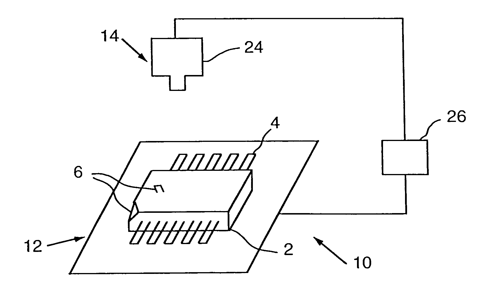
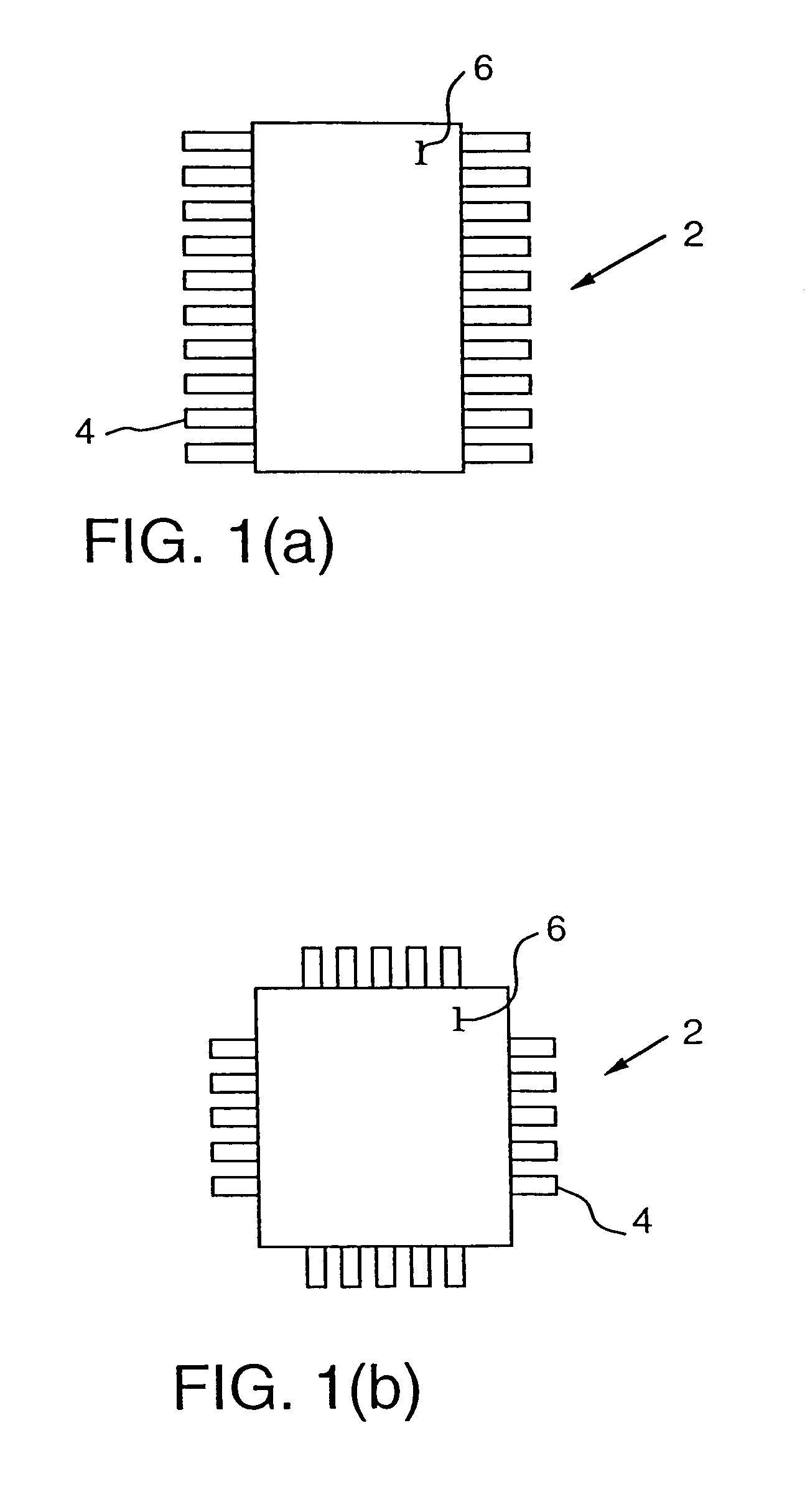
[0022]An apparatus 10 embodying the present invention will be described generally with reference to the drawings for the purpose of illustrating the present preferred embodiments of the invention only and not for purposes of limiting the same. The apparatus 10 generally includes a nest 12 and a detector 14. The nest 12 and detector 14 are used in combination with a component 2 having leads 4 by providing a fiducial marker 6 on the component 2, as shown in FIGS. 1(a)&(b), to determine or verify whether the leads 4 are properly aligned prior to placing the component 2 on a substrate 8. The fiducial marker 6 is provided on the component 2 in such a way to uniquely distinguish the alignment of the leads 4. Unless specifically stated, the term “fiducial marker” is meant to include any number and all types of marks that serve the distinguishing function, discussed above, either in isolation or combination. Such marks may include, but are not limited to, geometric shapes or characters that...


PUM

PropertyMeasurementUnit
physical appearanceaaaaaaaaaa
pressureaaaaaaaaaa
dimensionsaaaaaaaaaa

Abstract

A component transfer apparatus is provided. The component transfer apparatus comprises a pick and place machine having a component feed source and a movable pick head having access to the component feed source. A component alignment detector is directed toward the component feed source and a controller is coupled to the component alignment detector. The controller contains instructions which, when executed by the controller, cause the controller to compare the detected component alignment with a known component alignment.

Description

CROSS-REFERENCE TO RELATED APPLICATIONS[0001]This application is a divisional application of U.S. patent application Ser. No. 08 / 915,862, filed Aug. 21, 1997 now U.S. Pat. No. 6,085,407.STATEMENT REGARDING FEDERALLY SPONSORED RESEARCH OR DEVELOPMENT[0002]Not ApplicableBACKGROUND OF THE INVENTION[0003]The present invention relates generally to detecting the orientation of a body. More particularly, the present invention relates to alignment apparatuses and methods for determining whether leads on a semiconductor package are aligned in a predetermined alignment prior to placement on and attachment to a substrate. The invention can be generally used in conjunction with or integral to pick and place machines, such as surface mount placement machines, die attach machines, tape and reel production machines, wire bond machines, and the like, to verify proper lead alignment on components being placed by the machines.[0004]Solid state electrical devices are typically produced by attaching a ...

Claims


Application Information

Patent Timeline
Patent Type & Authority Patents(United States)
IPC IPC(8): H05K3/30H05K13/02H05K1/02
CPCH05K13/022H05K3/303H05K1/0269Y10T29/53052H05K2201/09918H05K2201/10689H05K2203/0195H05K2203/166Y10T29/53174Y10T29/4913Y10T29/49117Y10T29/49131Y10T29/53183Y10T29/49004Y10T29/53022Y10T29/53178Y10T29/53091Y10T29/49137Y10T29/49133Y10T29/49144Y10T29/53261Y02P70/50
Inventor GAMEL, DARRYLHINES, KREG W.
Owner MICRON TECH INC
Why Eureka
Try Eureka