
Vision component alignment apparatus

A technology for alignment devices and components, applied in measuring devices, optical devices, instruments, etc., can solve problems such as work efficiency limitations, and achieve the effect of saving working time

Inactive Publication Date: 2009-07-22
HUAZHONG UNIV OF SCI & TECH
View PDF2 Cites 1 Cited by
  • Summary
  • Abstract
  • Description
  • Claims
  • Application Information

AI Technical Summary

Problems solved by technology

Since the visual inspection mechanism needs to be placed and removed before each alignment placement, the operating mechanism needs to wait for the inspection operation to be completed before proceeding to the next step, and its work efficiency is greatly limited

Method used


Image

  • Vision component alignment apparatus
  • Vision component alignment apparatus
  • Vision component alignment apparatus

Examples


Embodiment Construction

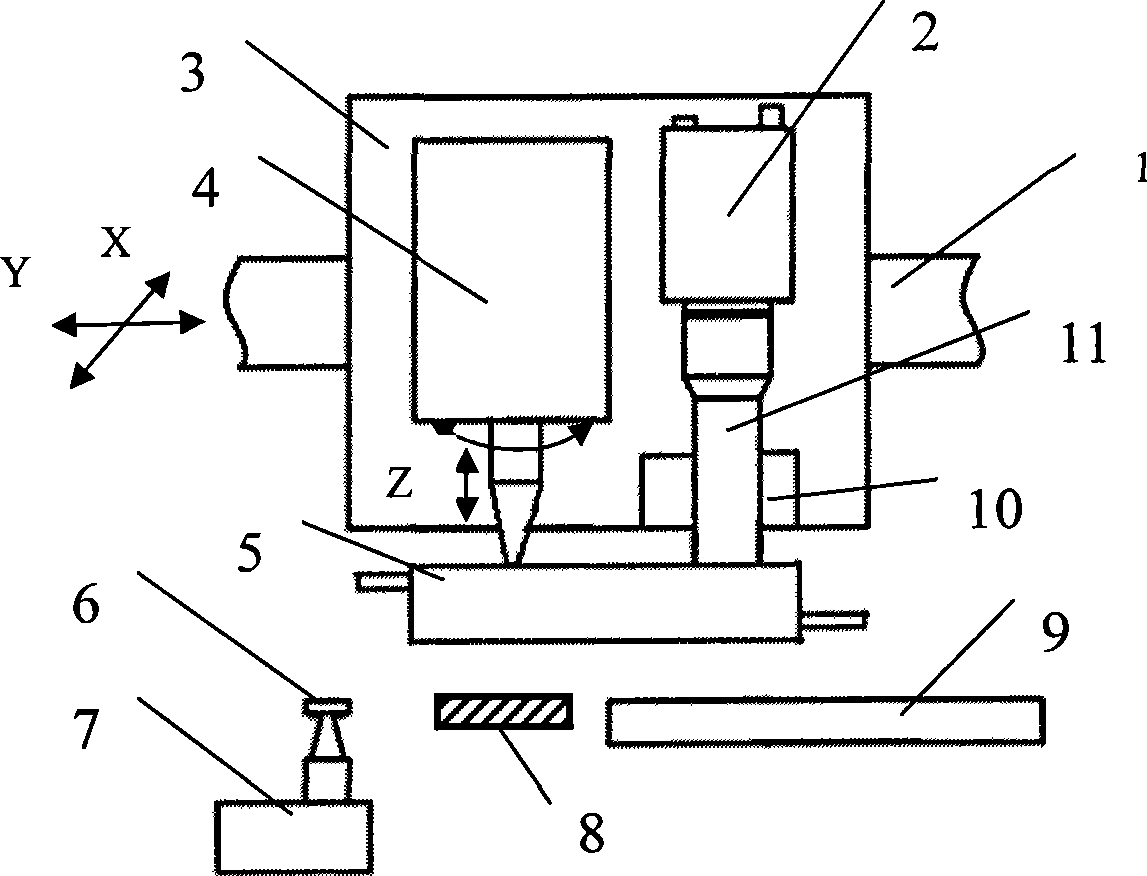
[0025] like figure 1As shown, the present invention consists of an X-Y motion mechanism, a component pick-and-place operating mechanism, a CCD electronic camera, a lens and its fixed adjustment mechanism, and a group of optical paths composed of oblique reflector groups and straight reflectors. Among them, the operating mechanism 4 that can vacuum absorb or adhere parts is installed on the support plate 3 fixed with the movement mechanism bracket 1, the movement mechanism can move along the X-Y direction, and the support plate 3 follows it; the execution part of the operation mechanism 4 can be Move up and down along the Z direction, and can rotate along the Z direction. The CCD electronic camera 2 and the optical lens 11 are screwed together through the interface, and the lens 11 and the electronic camera 2 are fixed on the support plate 3 by the lens fixing adjustment mechanism 10, which can follow the support plate 3; Adjust the distance from the lens 11 to the actual imag...


PUM


Abstract

An aligning device of visual components belongs to a device for measuring space position of objects and locating the objects, which solves the disadvantages that the existing device just has unidirectional identification or serial locating so as to realize bidirectional identification of components and mounting positions thereof as well as follow-up parallel locating. The aligning device comprises a movement mechanism, an operating mechanism, an electronic camera, a mechanism for fixedly adjusting lens and an optical path system. The movement mechanism can move along X-Y direction; the operating mechanism is installed on a support plate fixed with a bracket of the movement mechanism; an executive component of the operating mechanism moves up and down along Z direction and can conduct rotary movement along Z direction; the electronic camera is jointed together with the lens via a port by means of rotating, and is fixed on the support plate by a fixed adjusting mechanism; the optical path system is composed of two parts of an inclined reflector array and a horizontal reflector array, and the inclined reflector array is fixedly installed on the support plate and comprises two mutually parallel inclined reflectors having an angle of 45 degrees with a horizontal surface; a horizontal reflector platform is parallel to the horizontal surface and is installed between a component supply mechanism and a component mounting workbench. The visual aligning detection of components in installation can be simultaneously carried out in assembly process, thereby improving the accuracy and efficiency of installation operation.

Description

technical field [0001] The invention belongs to a device for measuring and positioning an object in space, and in particular relates to a vision component alignment device, which is used for accurate alignment of components in the assembly and packaging of electromechanical products in the automatic production process. Background technique [0002] In the automatic assembly process of electromechanical products, it is usually necessary to use an automatically controlled mechanical pick-up mechanism to pick up components (such as resistors, capacitors, integrated circuits, chips, etc.) from the component supply, transfer them to the installation position, and complete the alignment installation. When a component is picked up, its pose relationship may be uncertain, so it is necessary to obtain the relative pose information of the grabbed installed part. When the grabbing mechanism transfers the components to the installation position according to the command parameters, due t...

Claims


Application Information

Patent Timeline
IPC IPC(8): G01B11/00
Inventor 王瑜辉尹周平熊有伦熊波张少华
Owner HUAZHONG UNIV OF SCI & TECH
Learn More