Electronic component supply device and its mounting method

A technology for electronic components and installation methods, applied in electrical components, electrical components, metal processing equipment, etc., can solve problems such as efficiency and long time, and achieve the effect of shortening installation time

Inactive Publication Date: 2004-07-28
PANASONIC CORP
View PDF1 Cites 2 Cited by
  • Summary
  • Abstract
  • Description
  • Claims
  • Application Information

AI Technical Summary

Problems solved by technology

[0003] However, in such a configuration as above, the parts storage device selects a required parts storage part and moves it up and down and transports it from the take-out port, and the delivery head transports a given electronic part by sucking and hol

Method used


Image

  • Electronic component supply device and its mounting method
  • Electronic component supply device and its mounting method
  • Electronic component supply device and its mounting method

Examples


Embodiment Construction

[0016] In the following description of the present invention, the same reference numerals are used for the same parts in the drawings.

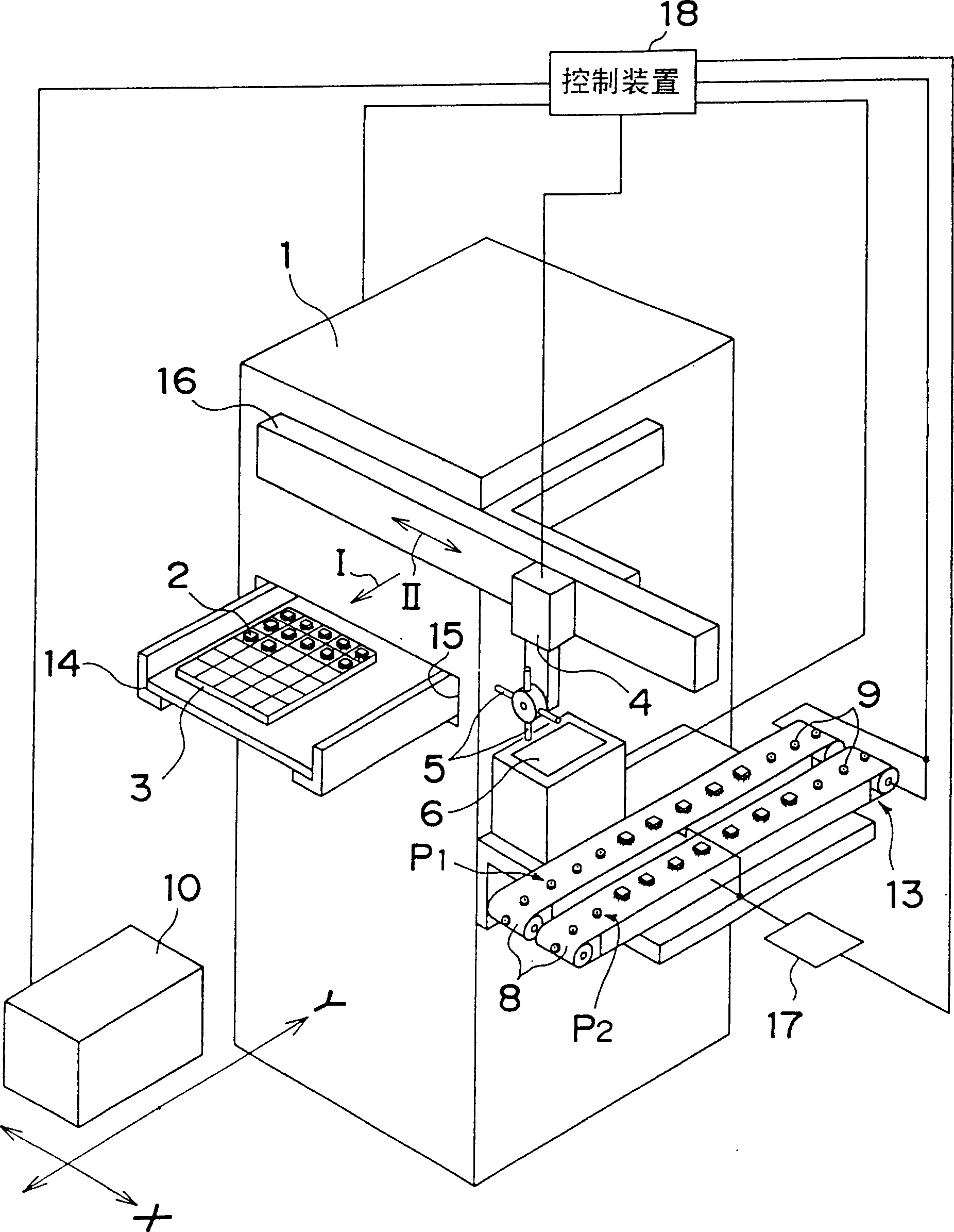
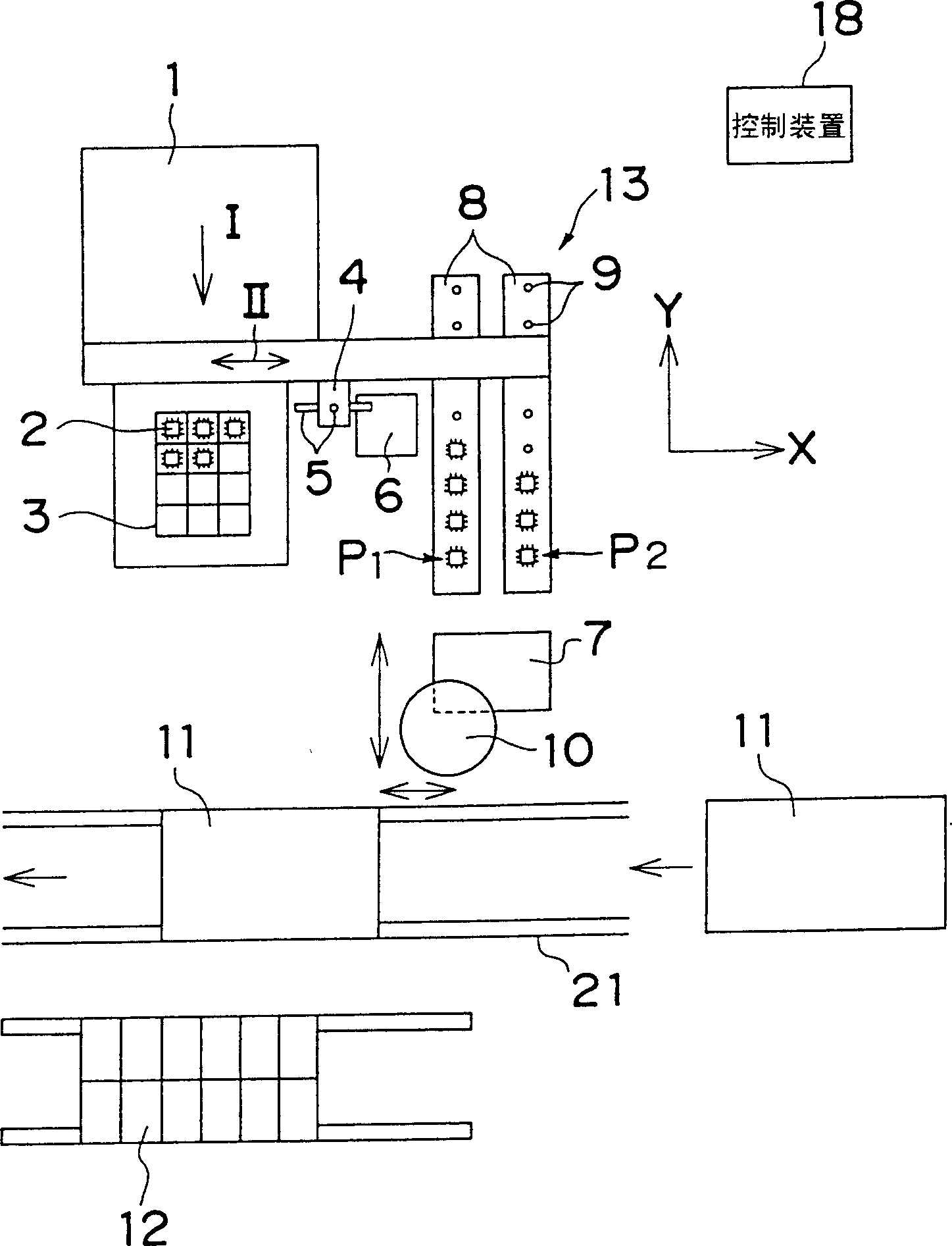
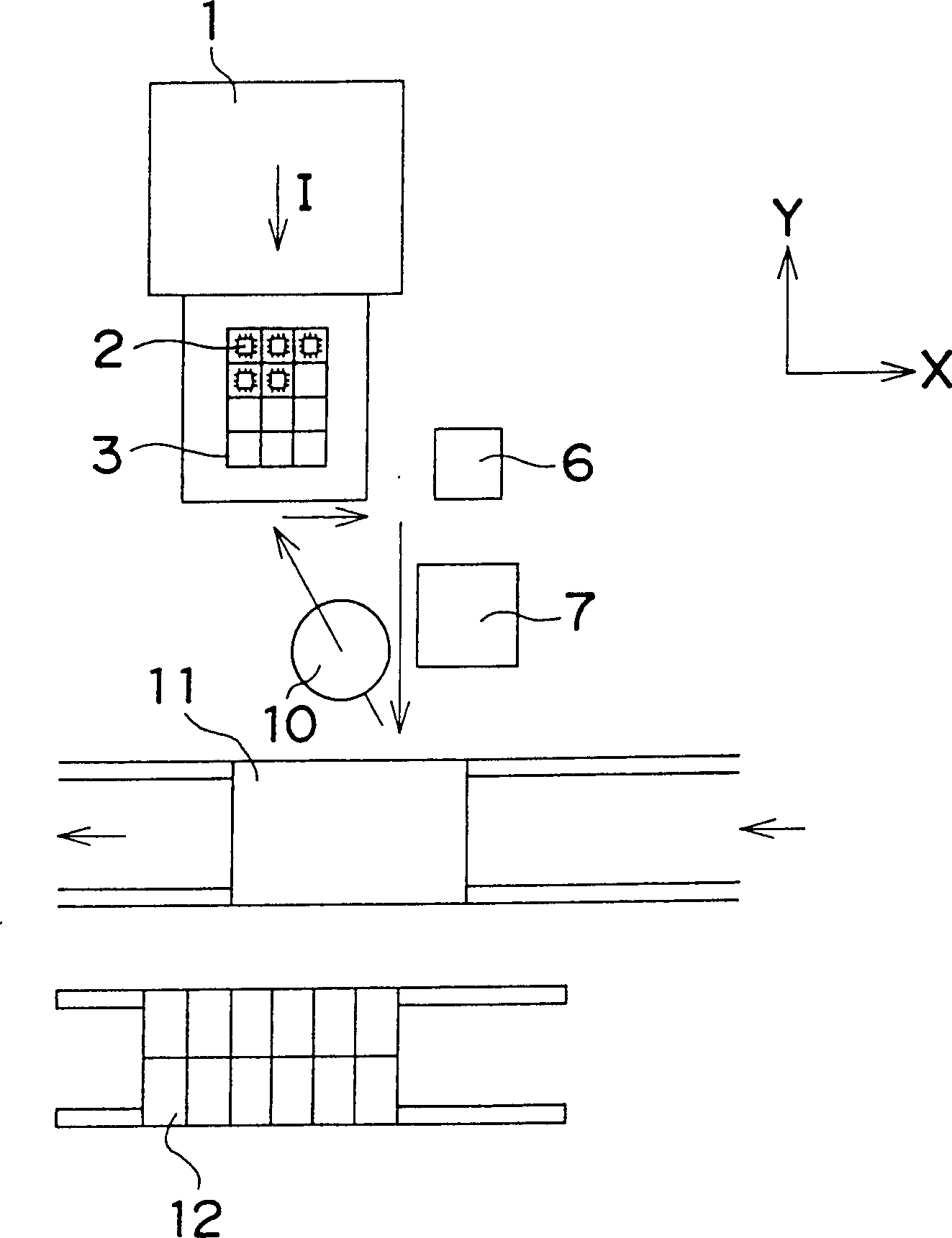
[0017] Refer to the attached figure 1 , 2 , to illustrate an embodiment of the present invention.

[0018] figure 1 Among them, the component storage device 1 stores the component storage parts 3 such as discs in which the electronic components 2 have been stored up and down in tens of stacked states, and the component storage parts 3 that have received the required electronic components are designated by the program, so that The component storage part support frame 14 of the component storage part 3 moves up and down and is transported to the take-out port 15, and is transported in the direction of the arrow I by the take-out port 15. The conveying head 4 has several kinds of conveying suction heads 5. According to the types of different electronic components 2, use the most suitable head to take out the electronic components 2 from the...


PUM


Abstract

The present invention has for its object to provide an apparatus and a method for feeding electronic components to a mounting head with high productivity. In order to accomplish the object of the present invention, an electronic component (2) taken out from a component storage section (3) by a transfer head (4) is held by means of a suction operation and transferred and inspected as to whether it is good or defective by a good/defective component inspecting device (6). Thereafter the electronic component is delivered to an alignment suction nozzle (9) on a component alignment section (13) The sequence of the above-operations is repeated, whereby the electronic components (2) inspected and then aligned in the order of mounting can be supplied to a mounting head (10). According to the present invention, a mount time for the electronic components in a mount process is greatly shortened, so that productivity is expected to be improved. The electronic components can be inspected before aligned in the order of mounting, which further enhances mount efficiency.

Description

technical field [0001] The present invention relates to an electronic component mounting method of an electronic component supply device used when mounting electronic components on a circuit board. Background technique [0002] image 3 A configuration diagram of a conventional electronic component mounting device is shown. The component storage part 3 which accommodates the desired electronic component 2 is selected from the component storage part 3 which accommodates tens of pieces, and is conveyed along the direction of arrow I. The mounting head 10 moves freely along the X and Y axis directions, holds the electronic component 2 through suction, and first detects the suction position of the electronic component 2 with the position detection camera 7, and then, the qualified product and non-conforming product inspector 6 inspects the lead wires to float out etc., carry out the inspection of qualified products and unqualified products of electronic components 2, and exclud...

Claims


Application Information

Patent Timeline
IPC IPC(8): B23P19/00H05K13/02H05K13/04
CPCY10T29/53178H05K13/0408Y10T29/53174Y10T29/49126Y10T29/53261Y10T29/53191Y10T29/4913Y10T29/49133H05K13/021H05K13/0434
Inventor 白川时夫
Owner PANASONIC CORP
Why Eureka
Try Eureka