Quick change blow mold tooling

a blow mold and tooling technology, applied in the field of blow mold tooling, can solve the problems that the change out or repair of conventional tooling can be a very tedious, time-consuming and labor-intensive process, and achieve the effects of reducing delivery time, reducing costs, and reducing machine down tim

Inactive Publication Date: 2008-06-03
R & D TOOL & ENG
View PDF12 Cites 27 Cited by
  • Summary
  • Abstract
  • Description
  • Claims
  • Application Information

AI Technical Summary

Benefits of technology

[0004]The present invention provides quick change tooling for the blow station of a bottle making machine so as to minimize machine down time, reduce costs, and decrease delivery time for the customer who purchases new tooling. One aspect of the invention comprises having cavity halves that are quickly and easily detachable from back plates so that the back plates can remain secured to the machine platens when the cavity halves are removed during change out or repair. Preferably, instead of a series of individually bolted-on cavity halves for each back plate, a single mold block having multiple cavity halves machined therein is provided for each back plate. Each mold block has locking studs that project from the backside thereof and fit into receiving holes in the backplate. Cam locking shafts are readily accessible from the side edges of the back plates and can be quickly and easily manipulated to lock and unlock the studs of the mold block.
[0005]In another aspect of the invention, a pushup plate that forms the bottoms of the mold cavities is quickly and easily detachable from the actuating mechanism of the machine. Preferably, instead of a series of individual bottom plugs or the like bolted onto the pushup plate, the pushup plate in accordance with the present invention comprises one long plate having a multitude of plugs or other projecting mold surfaces machined thereon. The pushup plate has a pair of locking studs at opposite ends thereof that are releasably received within respective socket members affixed to the pushup mechanism of the machine and which remain with the machine when the pushup plate is changed out. Each socket member has a quick release coupling associated therewith that allows the studs of the pushup plate to be firmly and positively secured to the machine during use yet quickly and easily removed and replaced without the use of tools.

Problems solved by technology

Change out or repair of conventional tooling can thus be a very tedious, time-consuming and laborious process.
It can also be costly, since no profit is generated by an idle machine.

Method used


Image

  • Quick change blow mold tooling
  • Quick change blow mold tooling
  • Quick change blow mold tooling

Examples


Embodiment Construction

[0027]The present invention is susceptible of embodiment in many different forms. While the drawings illustrate and the specification describes certain preferred embodiments of the invention, it is to be understood that such disclosure is by way of example only. There is no intent to limit the principles of the present invention to the particular disclosed embodiments.

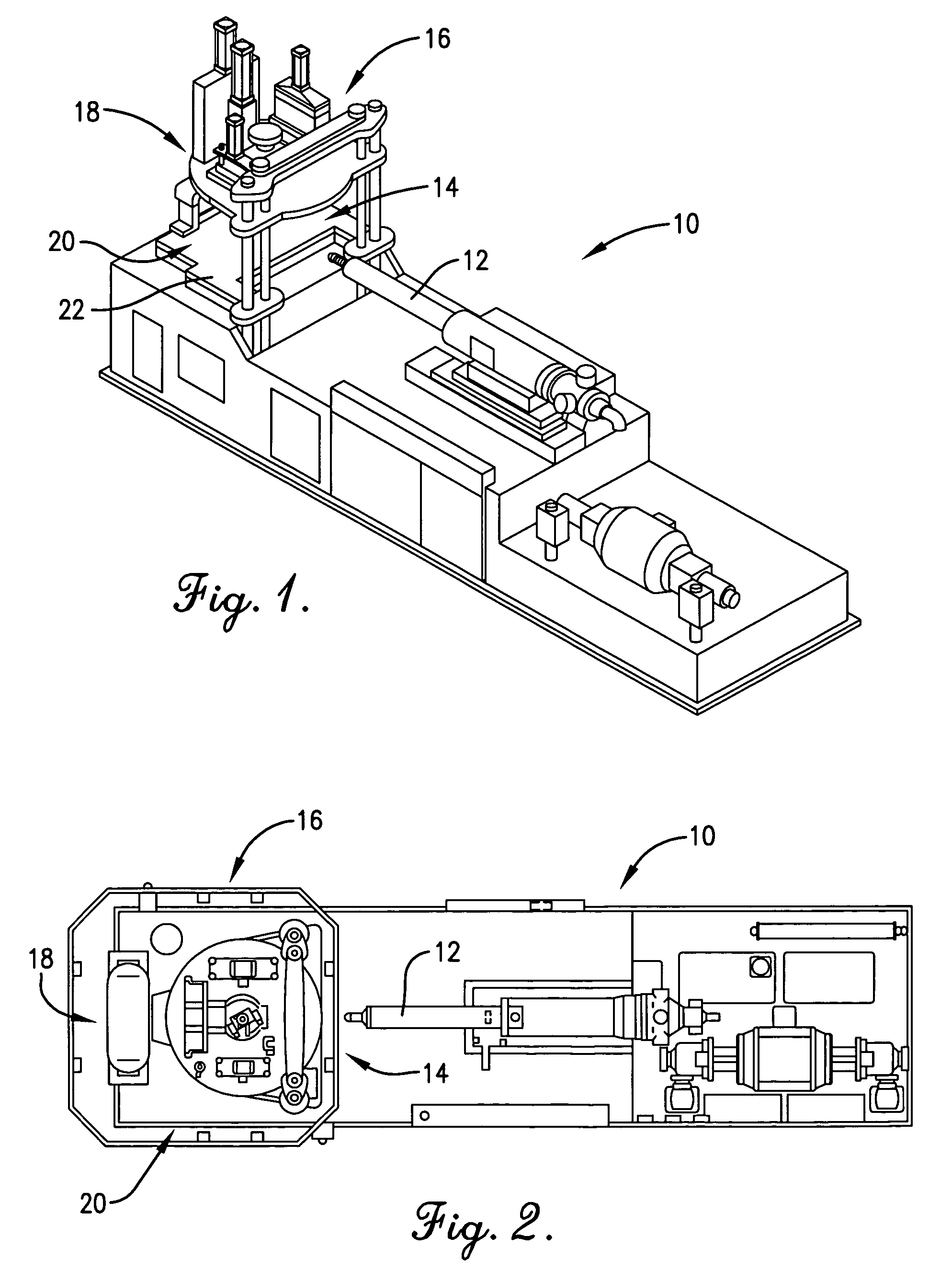
[0028]FIGS. 1 and 2 illustrate an injection stretch blow mold machine 10 with which the quick change tooling of the present invention has particular utility. However, it is to be appreciated that the principles of the present invention are not limited to the particular machine illustrated and described in this specification. The principles of the present invention may be beneficially applied to any bottle forming machine having a blow station utilizing tooling that must be changed out or repaired from time-to-time.

[0029]In the illustrated embodiment, machine 10 includes an injection nozzle 12 that injects molten plasti...


PUM

PropertyMeasurementUnit
angleaaaaaaaaaa
radius of curvatureaaaaaaaaaa
shapeaaaaaaaaaa

Abstract

Quick change blow mold tooling includes a pair of mold cavity blocks that cooperate to define a series of blow cavities. The tooling further includes a pushup plate having a series of bottom contours that plug the otherwise open bottoms of the cavities when the pushup plate is against the bottom of the mold blocks. Each mold block is quickly attached to and detached from its supporting back plate using studs that fit into receiving holes on the back plate and cam locking shafts that are accessible from opposite side edges of the back plates. The back plates thus remain secured to platens of the bottle forming machine during change out of the tooling. Similarly, the push up plate has a pair of locking studs projecting from the underside thereof that are received within socket members attached to the machine. The socket members are provided with quick release threaded couplers that can be locked and unlocked by hand.

Description

TECHNICAL FIELD[0001]This invention relates to blow mold tooling for use in the making of plastic bottles and the like.BACKGROUND AND SUMMARY[0002]Machines for blow molding plastic bottles have a blow station at which soft, warm preforms having the general appearance of test tubes become received within larger blow cavities having the shape of the finished bottle. Pressurized air, with or without a stretch rod, is injected into the soft preforms, causing them to stretch and expand out to the limits and configuration of the blow cavities. Typically, such blow cavities are formed by opposing mold halves that are opened and closed at the beginning and end of the blow cycle, and by bottom mold surfaces on a pushup plate that closes the bottom of the cavities when the mold halves are closed. When the mold halves are opened and the pushup plate is retracted (or the blown bottles are lifted from the pushup plate in some machines), the blown bottles can be moved out of the blow station to a...

Claims


Application Information

Patent Timeline
Patent Type & Authority Patents(United States)
IPC IPC(8): B29C49/48B29C49/56
CPCB29C49/42B29C49/06B29C49/48B29C2049/4856B29C2949/0715
Inventor FIELDS, RANDAL L.WHITNEY, MICHAEL D.
Owner R & D TOOL & ENG
Why Eureka
Try Eureka