Device for ensuring the installation of a component at the designated installation location of said component

a technology for ensuring the installation of components and components, applied in the direction of casings/cabinets/drawers, casings/cabinets/drawers, instruments, etc., can solve the problems of time-consuming and logistically complex, and achieve the effect of quick and easy detachment and replacemen

Active Publication Date: 2020-02-06
ROBERT BOSCH GMBH
View PDF0 Cites 1 Cited by
  • Summary
  • Abstract
  • Description
  • Claims
  • Application Information

AI Technical Summary

Benefits of technology

[0004]The scope of the present invention is to install a component at the designated installation location of said component in a system, all different components having the same plug connection and the installation of the component at the designated installation location of said component being permitted merely through the use of a mechanical coding component. The mechanical coding component is designed to be quickly and easily detachable and replaceable by another component.

Problems solved by technology

The disadvantage of this technology is that, in the case of a diversity of variants of the component, different plug types must be kept on hand and, if necessary, the entire plug device must be replaced by another plug device in order to change the variant.
This is logistically highly complex and may be time intensive.

Method used


Image

  • Device for ensuring the installation of a component at the designated installation location of said component
  • Device for ensuring the installation of a component at the designated installation location of said component
  • Device for ensuring the installation of a component at the designated installation location of said component

Examples


Embodiment Construction

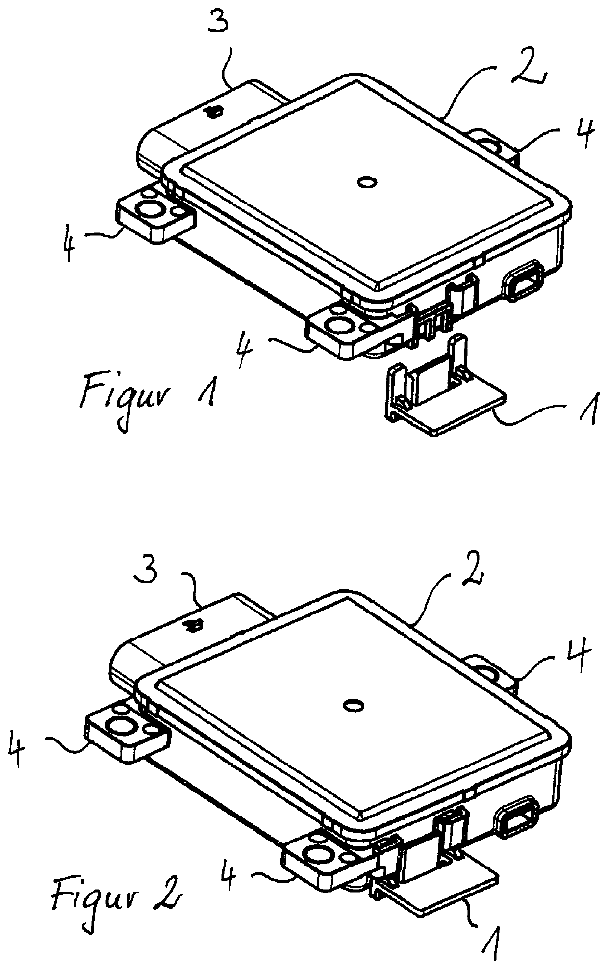
[0018]FIG. 1 shows a component 2 for installation in a system which may be, for example, a motor vehicle. This represented component 2 may be, for example, a sensor element which detects the vehicle surroundings and may be designed, for example, as an ultrasonic sensor or a radar sensor. Such sensors are equipped with different software or different parameters, depending on the designated installation location or vehicle model, so that the installation of a sensor does not need to take place at an arbitrary vehicle position, but rather at the proper intended position. Depicted component 2, which is designed as a radar sensor, by way of example, encompasses an electrical connection contact 3 on one side of the housing, with the aid of which electrical connections to other system components may be established, for example, in order to evaluate and further process the measuring signals from the sensor. The advantage of the present invention is that all components 2, despite different i...


PUM


Abstract

A device is described for ensuring the installation of a component at the designated installation location of said component in a system, made up of two parts, the first part of the device being attached to the component, and the second part of the device being attached to the system to which the component will be attached, and, during installation of the component into the system at the designated installation location of said component, the first part of the device and the second part of the device interlock precisely and enable assembly, in that the first part of the device and the second part of the device interact exclusively mechanically and exclusively enable the ensuring of the installation of the component at the designated installation location of the component in the system. When installing the component at a non-designated installation location on the system, the interaction of the first part of the device and the second part of the device, which form a poka-yoke system with each other, prevents installation.

Description

FIELD OF THE INVENTION[0001]The present invention relates to a device for ensuring the installation of a component at the designated installation location of said component in a system, made up of two parts, the first part of the device being attached to the component, and the second part of the device being attached to the system to which the component is attached, and, during an installation of the component into the system at the intended installation location of said component, the first part of the device and the second part of the device interlock precisely and enable assembly, in that the first part of the device and the second part of the device interact exclusively mechanically and exclusively enable the ensuring of the installation of the component at the proper installation location of said component in the system. When installing the component at a non-designated installation location on the system, the interaction of the first part of the device and the second part of t...

Claims


Application Information

Patent Timeline
Patent Type & Authority Applications(United States)
IPC IPC(8): H05K5/00H05K5/02G01D11/24F01N13/18
CPCH05K5/0073H05K5/0204F01N13/1844G01D11/245H05K5/0078
Inventor MOELLER, BIRGITDIHLMANN, MATHIASJAKOBY, RAINERKELLER, SINAWEIDINGER, THORSTEN
Owner ROBERT BOSCH GMBH
Why Eureka
Try Eureka