Flexible universal bladder tool for detecting leaks in a closed fluid system

a fluid system and flexible technology, applied in the direction of measurement devices, instruments, structural/machine measurement, etc., can solve the problems of fuel tank, engine manifold, intake and exhaust lines associated with motor vehicles, which are known to experience cracks, boles and fissures, and vehicle components to degrade, so as to achieve quick and easy detachability

Active Publication Date: 2018-03-22
CPS PRODS
View PDF3 Cites 1 Cited by
  • Summary
  • Abstract
  • Description
  • Claims
  • Application Information

AI Technical Summary

Benefits of technology

[0008]As an important feature of the flexible universal bladder tool herein disclosed, a flexible smoke delivery tube extends between the proximal and distal end caps. The flexible smoke delivery tube is detachably connected at its opposite ends to respective end cap fittings that are connected to the proximal and distal end caps, such that the flexible smoke delivery tube is surrounded by and coaxially aligned with the inflatable bladder when the bladder is in its relaxed, tube-like configuration. By virtue of the flexible nature of the smoke, delivery tube, the flexible bladder tool is adapted to be received by and bent around any of a variety of curved air ducts which lead to the system being tested for leaks. Moreover, the flexible smoke delivery tube is quickly and easily detachable from the first and second end cap fittings to be replaced by a different smoke delivery tube having a different length depending upon the size of the air duct and the corresponding size of the flexible universal bladder tool to be received therewithin.

Problems solved by technology

A fuel tank, the engine manifold, and the intake and exhaust lines associated with a motor vehicle are known to experience cracks, boles and fissures for a variety of reasons.
By way of another example, normal wear and tea and / or the caustic effects of fuel may, over time, cause these vehicle components to degrade.
In either case, because the damage caused is typically very small, such damage is often difficult to detect and locate to enable, repairs to be made.
The result in not being able to accurately locate and repair the damage is that fuel fluid and / or vapor may leak, whereby the environment is exposed to toxic fumes.
Similar damage in a normally sealed intake, or induction system, of a naturally-aspirated internal combustion engine can result in an air leak.
An air leak introduces extra air into the engine while in operation, since the engine creates vacuum.
This extra air will usually cause an, engine's computer management system to introduce additional fuel to compensate for the added air, resulting in unnecessary fuel consumption.
The same air leak in an older vehicle lacking an engine management system can result in an engine misfire, since the engine would be running lean, resulting in lack of engine performance and leading to engine damage.
A leak in the system could create sufficient pressure loss resulting in loss of engine power.
However, many intake and exhaust ducts and duct sections of a motor vehicle are either short in length or curved.
In the case of the known catheter apparatus referred to above, a test fluid delivery tube which is surrounded by the inflatable bladder and which carries smoke from the smoke machine to the system under test is undesirably rigid.
Consequently, this known catheter apparatus will not be capable of bending as would be required for the apparatus to be able to conform to the shape of and create a reliable seal against curved and bent duct sections.
Moreover, and as a result of the rigid, inflexible nature of the fluid delivery tube thereof, the aforementioned catheter apparatus is incapable of lateral movement as would also be required to produce a reliable seal against a curved or bent duct surface to which it is intended to be coupled.
Accordingly, this type of catheter apparatus is limited in its usefulness and application in performing leak tests in many systems that are found in the automotive and other industries.

Method used


Image

  • Flexible universal bladder tool for detecting leaks in a closed fluid system
  • Flexible universal bladder tool for detecting leaks in a closed fluid system
  • Flexible universal bladder tool for detecting leaks in a closed fluid system

Examples


Embodiment Construction

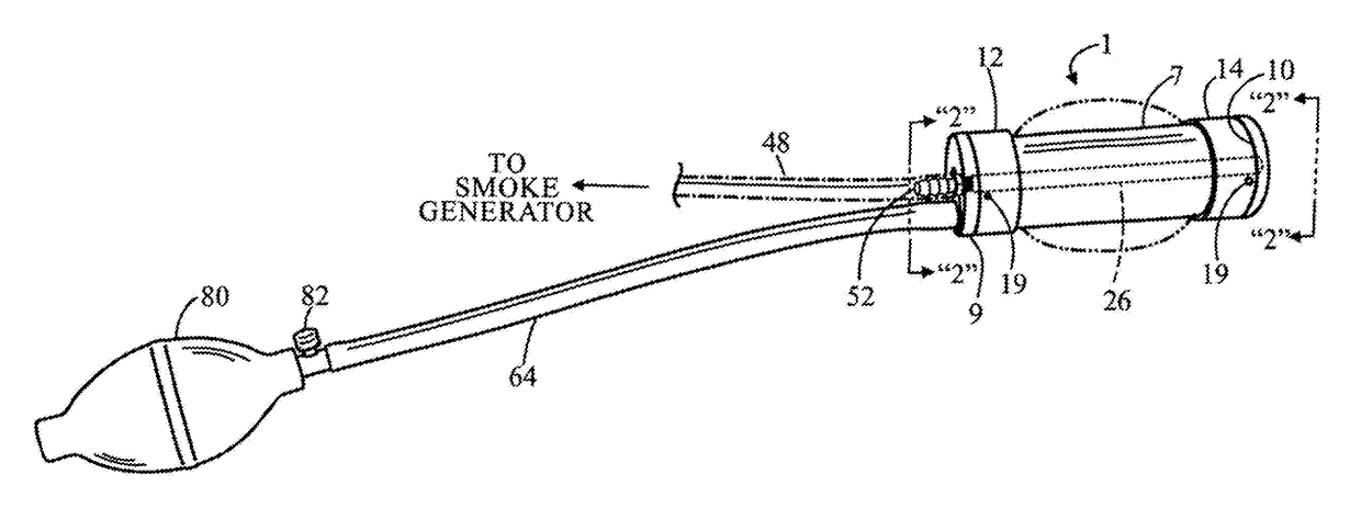
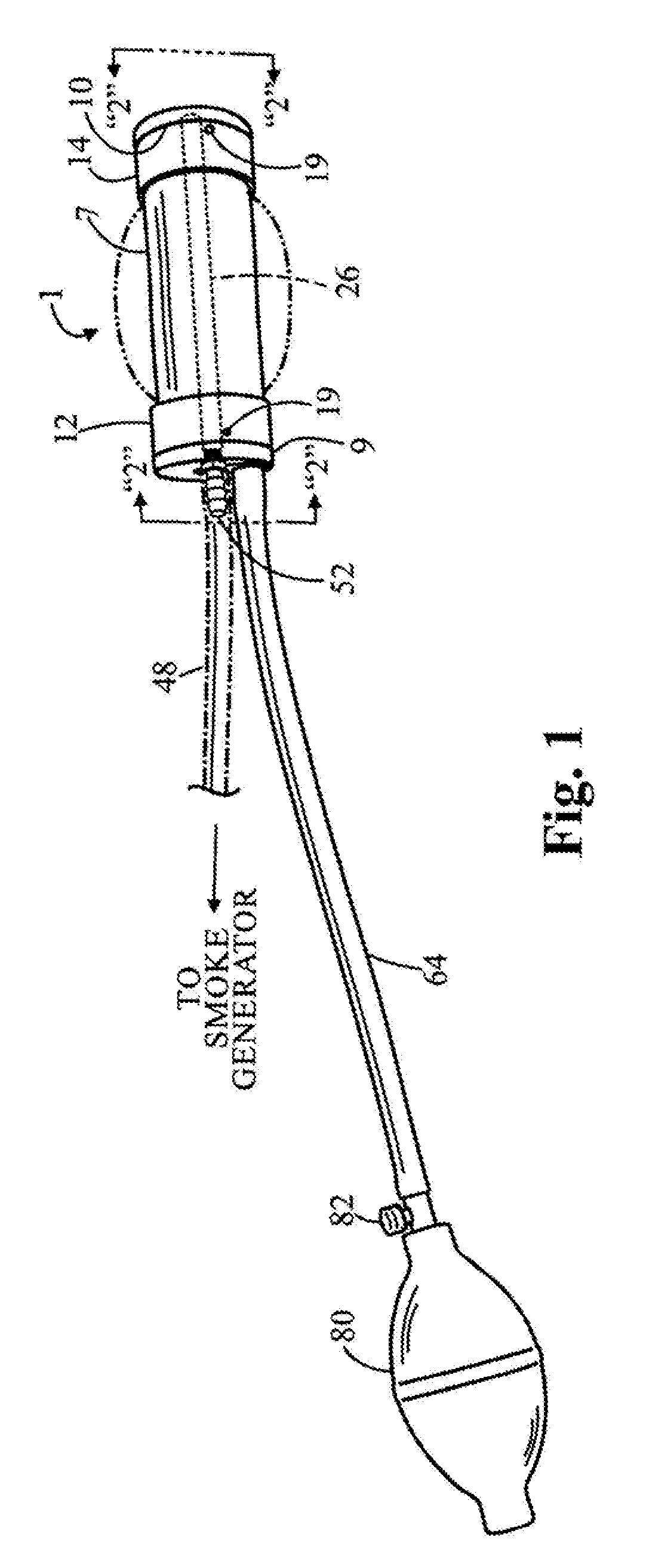
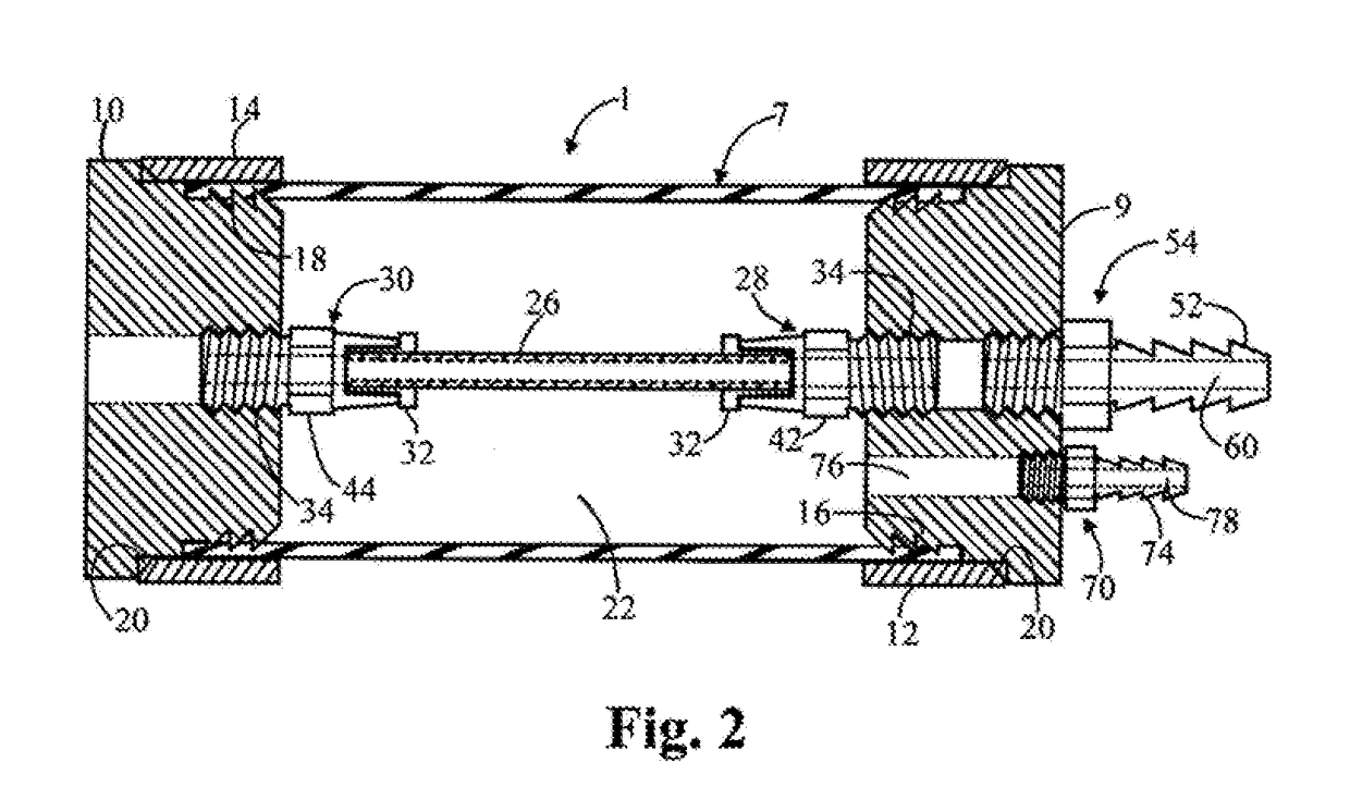
[0016]Referring initially to FIGS. 2-5 of the drawings, there is shown a flexible universal bladder tool 1 having particular application to be used to detect leaks in a closed fluid system such as that found in the automotive industry. By way of example only, the flexible bladder tool 1 is adapted to be removably received by a relatively short, straight neck 2 and then bend around and conform to the shape of a curved fluid (i.e., air) intake 3 that is common to the air intake system of some engines of a motor vehicle. By way of additional example, the closed fluid system to be tested for leaks can be a fuel system, exhaust system or air brake system of the motor vehicle which has an inlet tube 5 that communicates with the neck 2 and fluid intake 3 (best shown in FIGS. 4 and 5).

[0017]As will be explained in greater detail hereinafter the flexible bladder tool 1 is advantageously capable of being coupled to the straight neck 2, curved fluid intake 3, and inlet tube 5 regardless of the...


PUM


Abstract

A flexible universal bladder tool is disclosed to be coupled between a source of “smoke” and a fluid system to be tested for leaks, such as that found in the automotive industry. The bladder tool is an inflatable bladder that surrounds a flexible smoke delivery tube which communicates with the source of smoke and a fluid duct of the system under test. By virtue of the flexible nature of the smoke delivery tube, the inflatable bladder is adapted to be bent around any of a variety of curved fluid ducts. The flexible smoke delivery tube is detachable from the tool so that the tube can be quickly replaced with a different tube having a different length. The inflatable bladder is filled with fluid (e.g., air) to expand into sealing engagement with the fluid duet, and the system under test is pressurized with smoke supplied thereto by way of the flexible smoke deliver tube.

Description

BACKGROUND OF THE INVENTION1. Field of the Invention[0001]This invention relates to a flexible universal bladder tool to be interconnected between a generator of “smoke” and a closed fluid system to be tested for leaks, such as, that found in the automotive industry. The bladder tool, which includes a flexible smoke delivery tube that is surrounded by an inflatable bladder, is advantageously adapted to bend around and expand into sealing engagement against any of a majority of curved air intake ducts leading to the system under test.2. Background Art[0002]A fuel tank, the engine manifold, and the intake and exhaust lines associated with a motor vehicle are known to experience cracks, boles and fissures for a variety of reasons. By way of a first example, a rock or another object encountered along a roadway may strike the undercarriage while the vehicle is in motion. By way of another example, normal wear and tea and / or the caustic effects of fuel may, over time, cause these vehicle ...

Claims


Application Information

Patent Timeline
Patent Type & Authority Applications(United States)
IPC IPC(8): G01M3/20G01M3/02
CPCG01M3/022G01M3/20
Inventor MCCOLLOM, GREGORY M.SAFFIE, JIM E.
Owner CPS PRODS
Why Eureka
Try Eureka