Systems and methods for multi-modality imaging component alignment

a multi-modality imaging and component technology, applied in the field of multi-modality imaging system alignment, can solve the problems of unsuitable registration, difficult maintenance and storage, large vqc phantoms, etc., and achieve the effect of accurate alignmen

Active Publication Date: 2018-08-14
GENERAL ELECTRIC CO
View PDF6 Cites 2 Cited by
  • Summary
  • Abstract
  • Description
  • Claims
  • Application Information

AI Technical Summary

Benefits of technology

[0006]In one embodiment, a method comprises performing a plurality of scans of an object with a first modality and a second modality, wherein the object is positioned in a different orientation in each of the plurality of scans, calculating a plurality of alignment parameters of a first modality unit and a second modality unit based on the plurality of scans, and adjusting alignment of the first modality unit and the second modality unit based on the plurality of alignment parameters. In this way, components of a multi-modality imaging system may be accurately aligned using a simple phantom.

Problems solved by technology

Even if the CT and PET are perfectly aligned, a misaligned table will produce different artifacts in the CT and PET volumes, which cannot be properly registered.
However, VQC phantoms are generally large, expensive, and challenging to maintain and store, which is unnecessarily burdensome considering that VQC phantoms are only occasionally used.

Method used


Image

  • Systems and methods for multi-modality imaging component alignment
  • Systems and methods for multi-modality imaging component alignment
  • Systems and methods for multi-modality imaging component alignment

Examples


Embodiment Construction

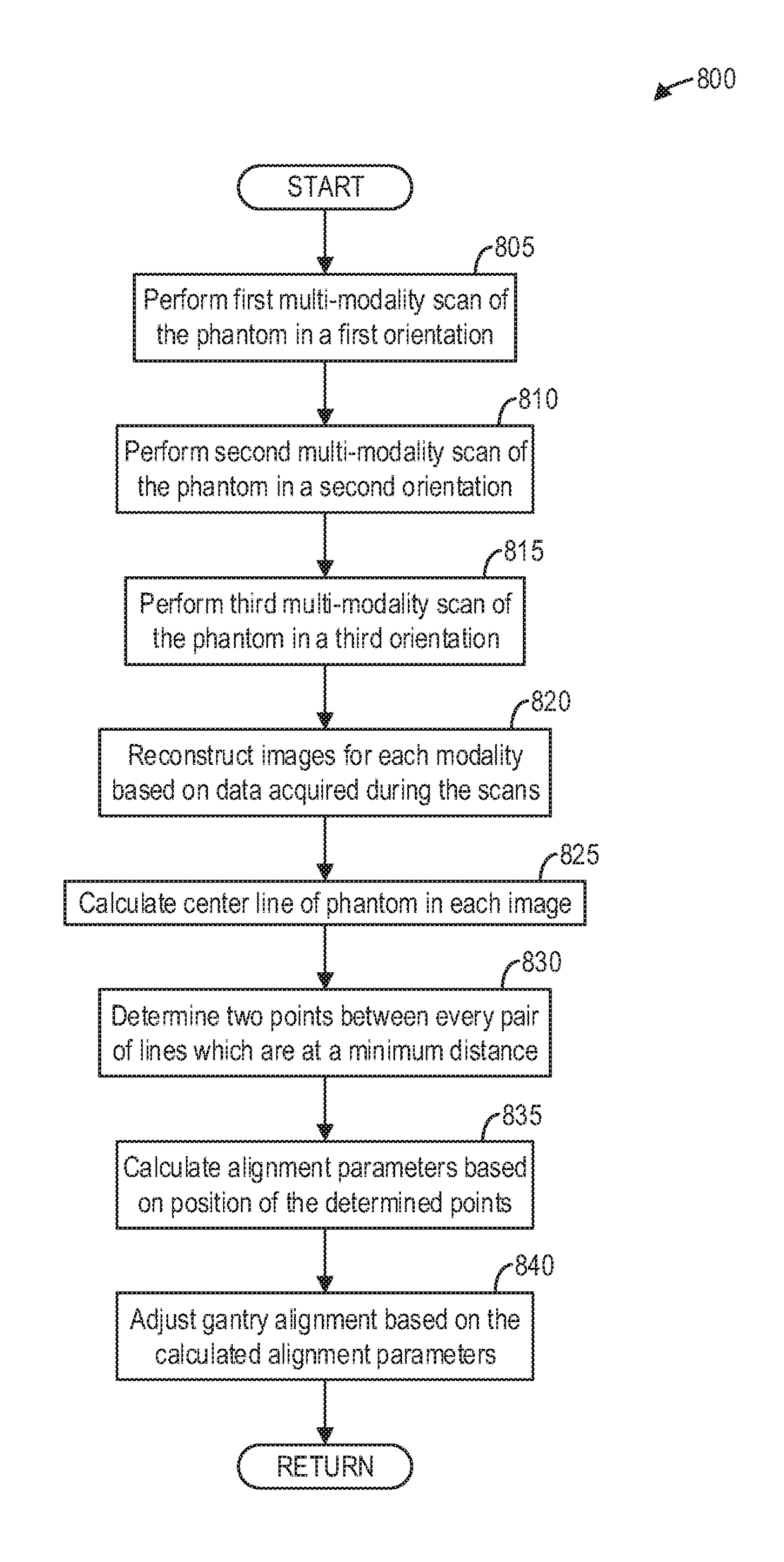
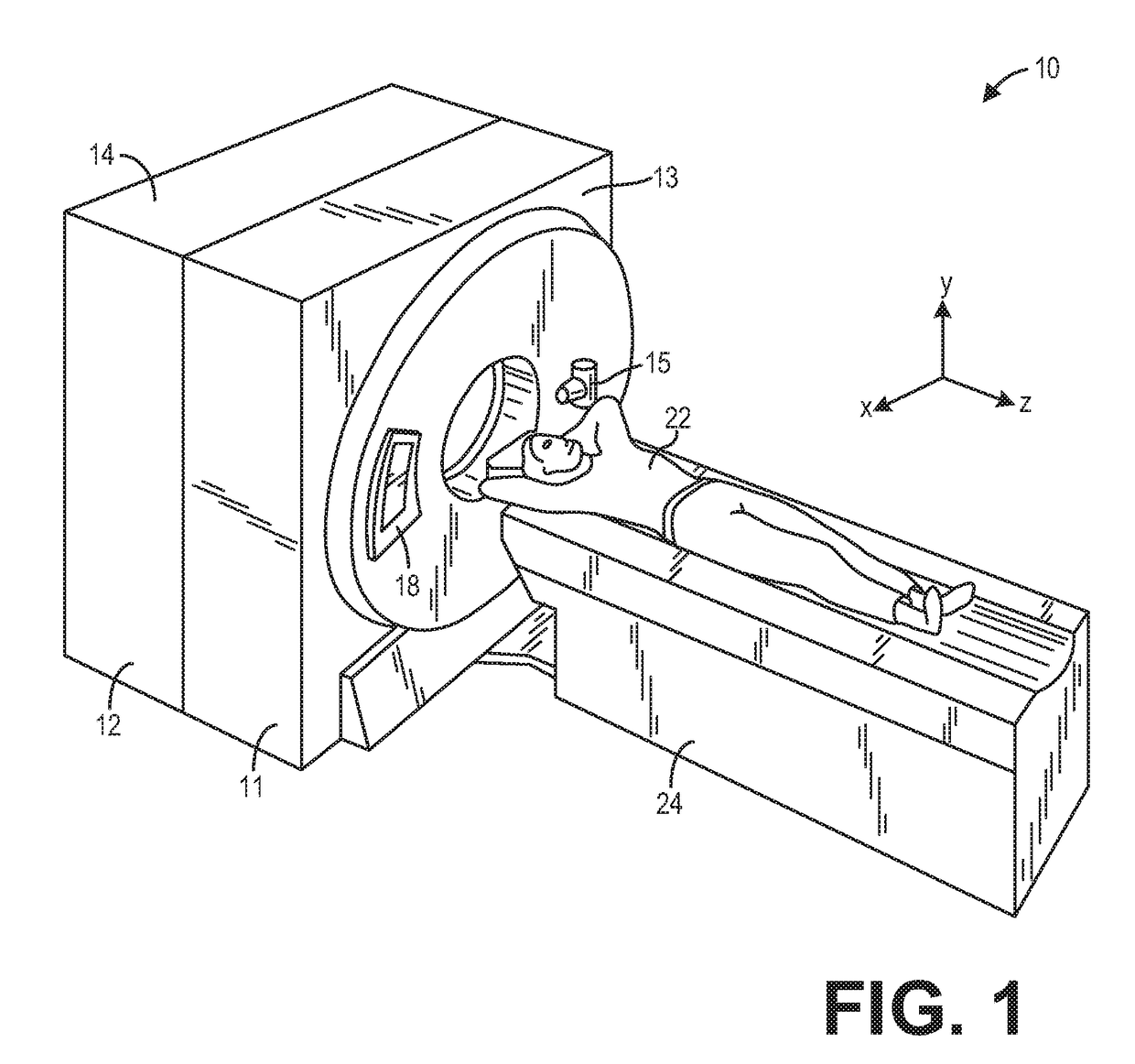
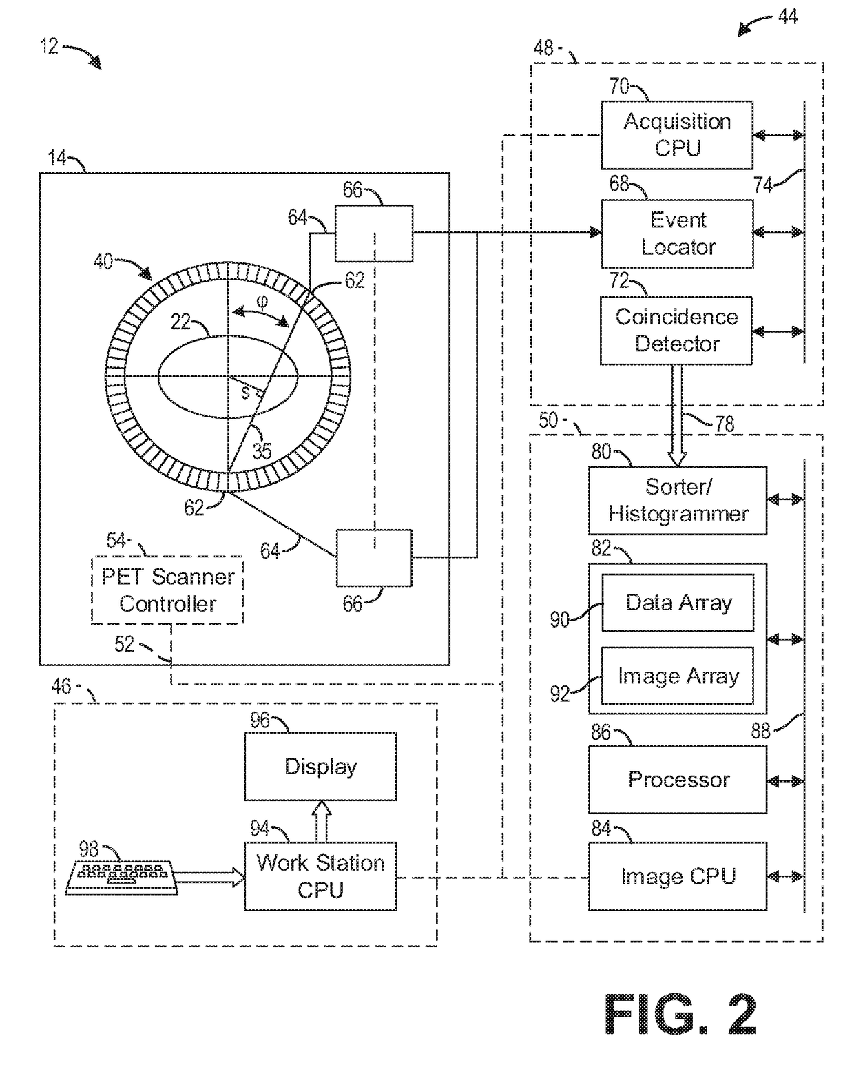
[0020]The following description relates to various embodiments of a multi-modality imaging system. In particular, systems and methods are provided for aligning components of a multi-modality imaging system, such as the multi-modality imaging system depicted in FIGS. 1-3. An annulus phantom, such as the phantom depicted in FIGS. 4A-4C, may be scanned in several orientations, such as the orientations depicted in FIGS. 5-7. A method for aligning imaging system components, such as the method depicted in FIG. 8, includes calculating a plurality of alignment parameters based on images reconstructed based on scans of the annulus phantom in the different orientations. The plurality of alignment parameters are depicted in FIGS. 9-11.

[0021]Though a PET / CT system is described by way of example, it should be understood that the present techniques may also be useful when applied to images acquired using other imaging modalities, such as tomosynthesis, MRI, C-arm angiography, and so forth. The pr...


PUM


Abstract

Methods and systems are provided for aligning components of a multi-modality imaging system. In one embodiment, a method comprises performing a plurality of scans of an object with a first modality and a second modality, wherein the object is positioned in a different orientation in each of the plurality of scans, calculating a plurality of alignment parameters of a first modality unit and a second modality unit based on the plurality of scans, and adjusting alignment of the first modality unit and the second modality unit based on the plurality of alignment parameters. In this way, components of a multi-modality imaging system may be accurately aligned using any phantom from which a unique line can be extracted in each modality scan.

Description

FIELD[0001]Embodiments of the subject matter disclosed herein relate to multi-modality imaging systems, and more particularly, to alignment of multi-modality imaging system components.BACKGROUND[0002]Multi-modality imaging systems are capable of scanning using different modalities, including but not limited to Positron Emission Tomography (PET) and Computed Tomography (CT). While some of the same hardware is utilized to perform different scans (e.g., an image produced by PET is processed and displayed respectively by the same computer and display as an image produced by CT), the data acquisition systems (hereinafter sometimes referred to as a “modality unit”) are different. For example, on a CT / PET system, a radiation source and a radiation detector are used in tandem to acquire CT data, while a radiopharmaceutical is typically employed in tandem with a PET camera to acquire PET data.[0003]In such multi-modality systems, such as an integrated PET / CT system, there is an inherent regi...

Claims


Application Information

Patent Timeline
Patent Type & Authority Patents(United States)
IPC IPC(8): G06T7/60G06T7/80G06T7/00
CPCG06T7/60G06T7/0012G06T7/80G06T2207/10104G06T2207/10081G06T7/30
Inventor JAIN, NITINSINHA, NEELAMSTEARNS, CHARLES
Owner GENERAL ELECTRIC CO
Why Eureka
Try Eureka