[0002] It is well known to provide
prosthetic joint components for replacing damaged and deteriorating joints. Typical joint replacements require resection of distal or proximal end of one or more of the bones forming the joint to be replaced to permit the prosthetic device to be firmly attached to the bone without altering the length of the limb in which the joint is being replaced.
Joint component manufactures have recognized the benefits to be derived from
joint replacement procedures that require less invasive surgeries with smaller incisions and more kinematically correct implants. Additionally, as younger patients are receiving joint replacements, there is a desire to provide joint replacements that allow the patient to recover from the replacement
surgery more quickly, provide better function and are more durable.
[0006] Benefits of uni-compartmental knee
arthroplasty over
total knee arthroplasty include 1) faster
recovery, 2) less pain, 3) greater
range of motion, 4) greater feeling of normalcy, 5) better alternatives when the
prosthesis wears out, 6) no blood transfusions and 7) no need for blood thinners. Many of these benefits arise because with a uni-compartmental arthroplasty the surgery is less extensive, the incision is smaller, and there is less
tissue trauma than in a TKA. A primary TKA will usually last 10-15 years. When it fails it must be replaced with a Revision TKA (RTKA). RTKAs have a high
complication rate and don't last as long as primary TKAs. The uni-compartmental arthroplasty buys time. When it wears out it is replaced by a TKA. Patients may never need an RTKA or if they do, they generally will have gotten many more years use out of their TKA. By utilizing a uni-compartmental arthroplasty instead of a TKA, patients of any age can benefit.
Older patients benefit from the reduced severity of the procedure and easier
recovery. Younger patients benefit because when the
prosthesis eventually fails (all prostheses fail faster in younger patients), they will be able to have it replaced with the better primary TKA as opposed to the less desirable RTKA.
[0007] Some prior art uni-compartmental knee systems have provided either limited
instrumentation, making reproducible alignment difficult, or bulky instrumentation which requires more intrusive surgery. A few prior art uni-compartmental knee systems are designed with bone conserving femoral and tibial components that provide reproducible results utilizing a
minimal incision. The resurfacing femoral
implant conserves more quality
bone stock compared to contemporary full resection femoral implants.
[0009] The technical challenges of less invasive uni-compartmental
knee surgery are becoming more apparent, even for the specialist arthroplasty surgeon. CAS technology has a clear role to play in
less invasive surgery. CAS technology provides enhanced surgical vision which optimizes
visualization of the critical anatomical landmarks, irrespective of the length of the incision. CAS technology offers the surgeon a level of vision and control that is difficult to achieve with non-CAS enabled, less invasive, procedures. With the key
anatomy fully visualized, finger-tip instrument adjustment allows the surgeon to transfer on-screen planning to the table with greater precision. Virtual planning and kinematic assessment
software provided with CAS technology allows
implant positioning for each patient prior to any bone cuts being made.
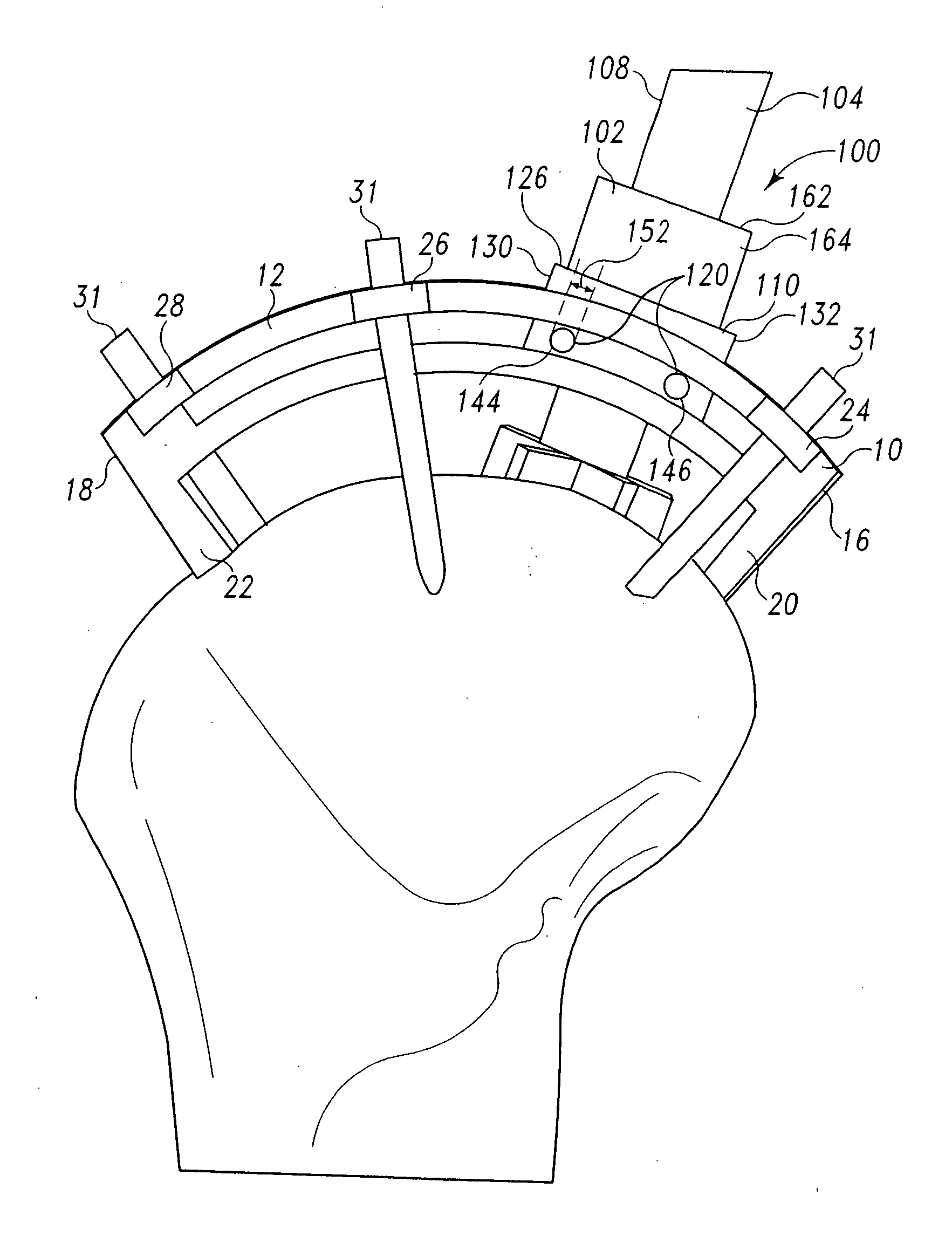
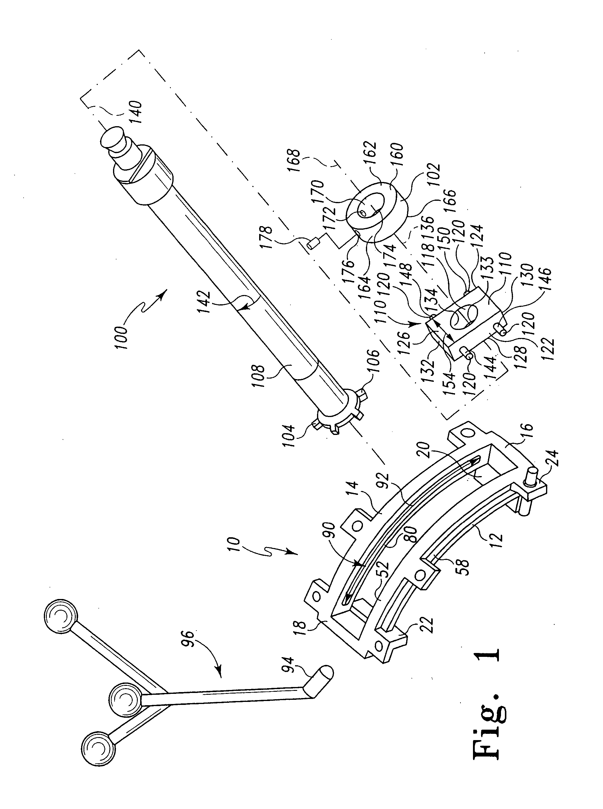
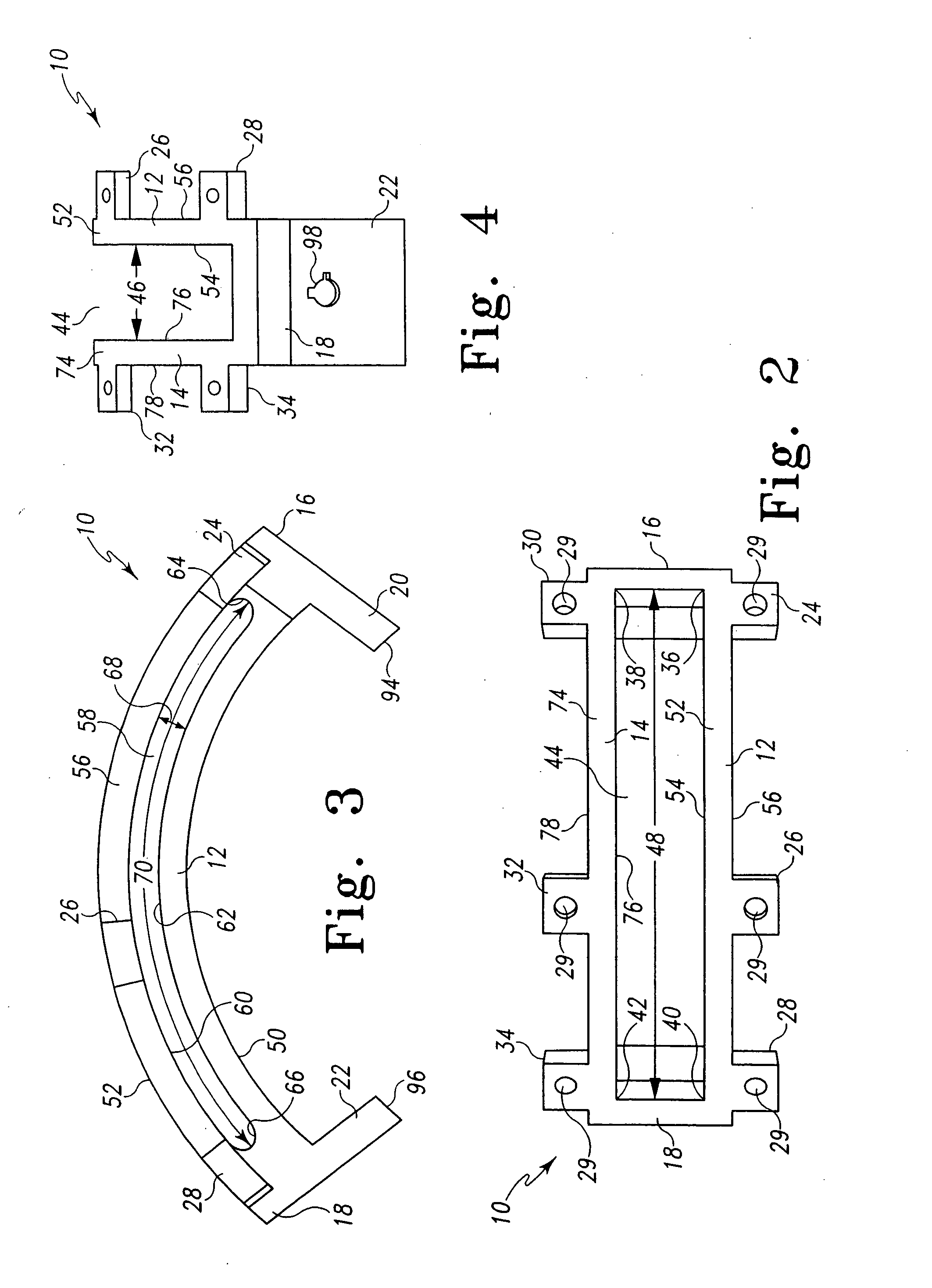
[0010] The disclosed invention provides guides and a cutting tools configured to follow the guides to resect a bone to receive a
surface replacement implant. The guide includes features to maintain the correct alignment of the
cutting tool while providing sufficient freedom to create cuts having the desired depth for receiving a
surface replacement prosthesis. The guides and cutting tools are configured to be effectively used in a
minimal incision procedure while still offering the surgeon the alignment guides needed for consistent results. The disclosed guides are configured for utilization with CAS technology. Thus, reproducible outcomes are possible within a
minimal incision.
[0011] According to one aspect of the disclosure, a bone resection tool for resecting an end of a bone along a surface having a curvature comprises a guide, a cutting tool and a track follower. The guide is configured to be removably attached in a
fixed position to the end of the bone. The guide is configured to include a track exhibiting a curvature generally corresponding to the curvature of the surface to be resected in the bone. The cutting tool includes a cutting face. The track follower is configured to couple to the cutting tool and cooperate with the track to facilitate reciprocation of the cutting tool relative to the guide to induce the cutting face to resect the bone along the surface having the curvature.

