High temperature nanofilter, system and method

a nanofilter and high temperature technology, applied in the field of high temperature filters, can solve the problems of high restriction, high thermal mass, low capacity, etc., and achieve the effects of less laminar flow, less adversely affecting the performance of the final filter product, and more structural stability

Inactive Publication Date: 2006-05-30
3M INNOVATIVE PROPERTIES CO +1
View PDF128 Cites 218 Cited by
  • Summary
  • Abstract
  • Description
  • Claims
  • Application Information

AI Technical Summary

Benefits of technology

[0025]Another possibility is to use corrugation for producing a diesel emission control filter. In this method, corrugated rollers are used to imprint a shape onto the media, instead of creasing and folding the media as is done with other pleating methods. The limitation of the noted corrugation method is that the pleats have a sinusoidal cross- section, rather than triangular or trapezoidal. As above noted, triangular or trapezoidal flutes or channels are desired, with cross-sectional geometries which are more structurally stable and provide for more laminar flow.
[0026]In one aspect of the '490 patent, a star gear pleating method is used to produce the pleated media pre-form for a diesel engine control filter. Particularly designed interlocking gears pass the media between one or more sharp tips of a gear tooth on one gear and a particularly formed root of the opposing gear. The teeth can be modified to provide triangular or trapezoidal pleats. The gears fold and gather the media withou...

Problems solved by technology

These suffer a variety of shortcomings, depending on the specific design, including high thermal mass, high restriction, low capacity, and poor durability.
Conventional methods, including score-roll pleating and corrugation, cannot produce media with the noted desired geometry and structure.
The inherent stiffness of the media causes the media to fold or crease into pleats along the score lines.
For this reason, score-roll pleating is unsuitable for pliable media with insufficient stiffness, such as the ceramic media used in the above noted diesel emission control filter.
Another limitation is that the desired small pleat heights, e.g. less than 10 mm, cannot be obtained by the noted score-roll pleating method.
Furthermore, creasing along the noted score lines can damage the media pleat tips for some types of filter media, including that used for the noted diesel emission control filter.
The limitation of the noted corrugation method is that the pleats have a sinusoidal cross- section, rather than triangular or trapezoidal.
As the media is released from the interlocking gears, it is directed forward and out of the gears by guide bars which prevent the media from tending to follow the gears and become damaged.
Particulate soot combustion byproducts have been ...

Method used


Image

  • High temperature nanofilter, system and method
  • High temperature nanofilter, system and method
  • High temperature nanofilter, system and method

Examples


example i

[0154]10.5 grams of alumina fibers having an average fiber diameter of 3 microns and length of about 0.01 to 10.0 mm was dispersed in 5000 grams of water to form a slurry or suspension. 1.8 grams of wood fibers were mixed along with 1.8 grams of KEVLAR® wet-pulp fibers in 1000 grams of water in a Waring blender and then added to the alumina fiber. Also added to the suspension was 2 grams of an acrylic latex binder containing 50% solids. The pH was reduced to 6.0 with the addition of aqueous alum. The suspension was further diluted with 15,000 grams of water. The slurry was then formed into a paper-like sheet using a conventional 12″×12″ square papermaking mold machine. The sheet was dried at a temperature of 150° C. and the resulting dried sheet had a porosity of 90%, a mean flow pore diameter of 12 microns, a weight of 150 grams per square meter, and a thickness of 0.95 mm.

[0155]Multiple sheets of paper were cut into sections each having a width size of 7.5 cm. One strip was corrug...

example ii

[0160]A green filter structure was prepared as described in Example I. The filter structure was then dipped in a 7% by weight colloidal suspension of alumina and the part was then air dried and then heated to a temperature of 250° C. to remove all solvents and dehydrate water. Subsequently, the part was fired at a temperature of 1100° C. in air to remove all the organic components, thus resulting in a structure consisting primarily of haphazardly arranged ceramic fibers and inorganic binders.

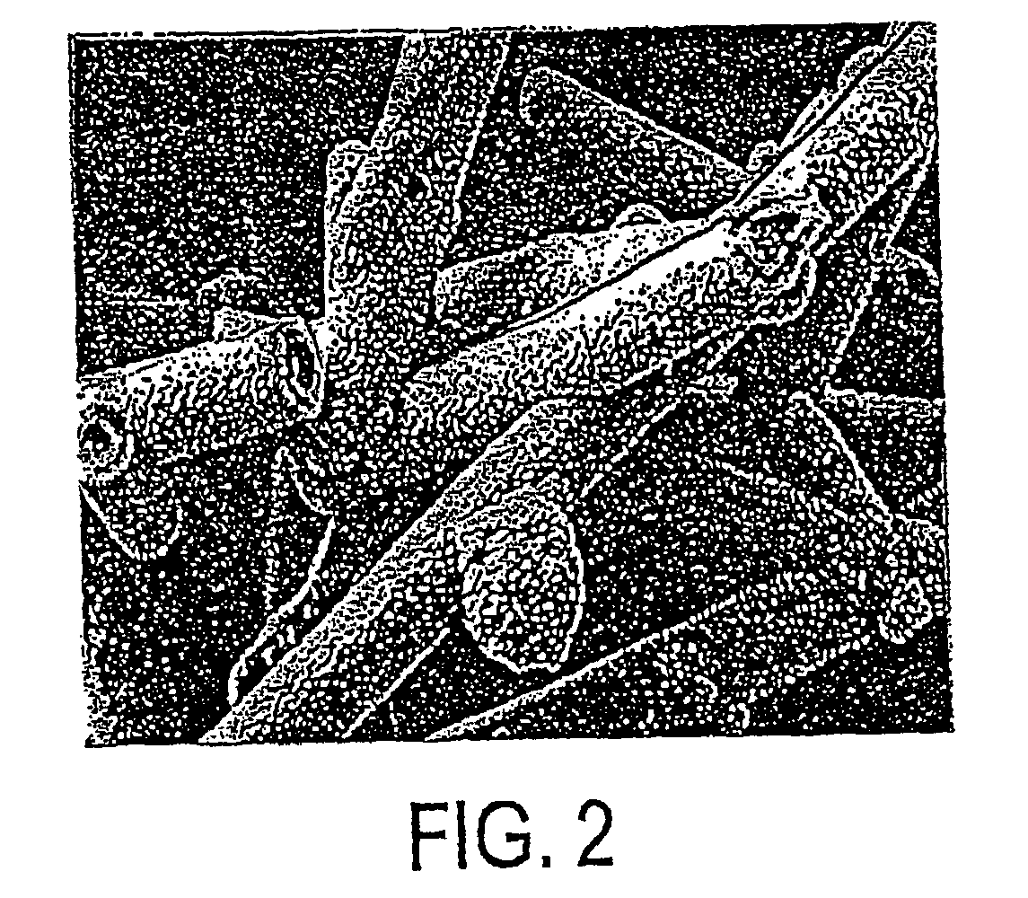
[0161]The filter structure was then subjected to a chemical vapor deposition process to coat the fibers and the intersections between fibers with a coating of silicon carbide, as described in Example 1.

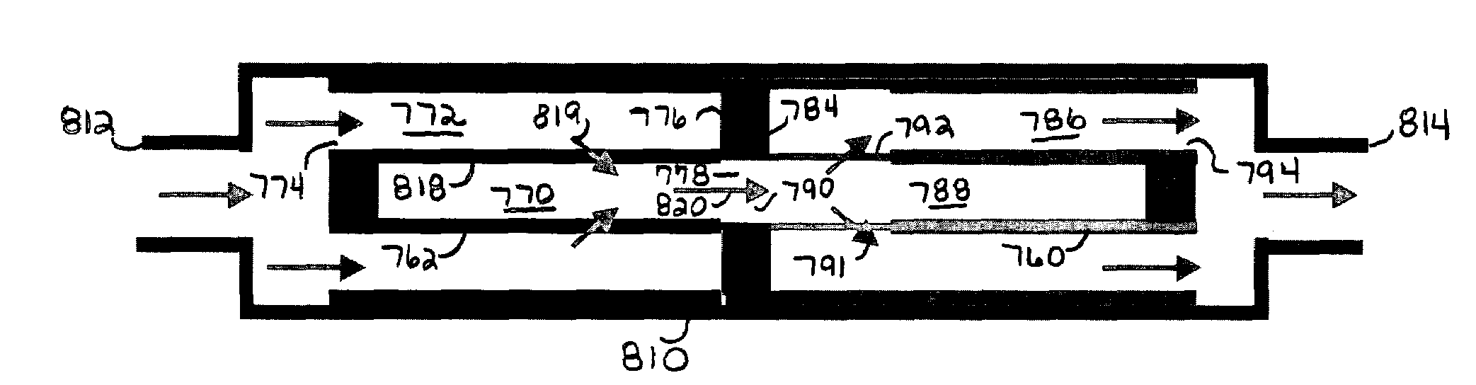
[0162]The '490 patent provides a green uncured pre-form 10, FIG. 1, for an exhaust aftertreatment control filter. The pre-form includes first and second sheets 12 and 14 of regenerable filter material, as described above. Sheet 14 has a plurality of pleats such as 16 defined by wall segments 18, 2...

example 1

[0263]A primary dispersion was prepared by charging 87.0 g Dispersion III to a beaker and adding 13.0 g of isopropyl alcohol while stirring with a magnetic stir bar. A series of 9 cm by 9 cm green, ceramic fiber, paper coupons were impregnated by immersing the entire coupon into the primary dispersion on one side for 10 seconds, turning the coupon over and immersing it in the dispersion for an additional 10 seconds. After impregnation, the coupons were hung vertically and air dried overnight at room temperature (about 25° C.). The air dried coupons were then dried in a vented oven at 100° C. for 30 minutes, and then calcined and fired in a vented box furnace in air using the following heating sequence: room temperature to 500° C. in 3 hours; hold at 500° C. for 1 hour; heat from 500° C. to 1100° C. in 2 hours; hold at 1100° C. for 1 hour; cool in furnace to room temperature. The fired coupons are referred to as Coupon A.


PUM

PropertyMeasurementUnit
Temperatureaaaaaaaaaa
Fractionaaaaaaaaaa
Lengthaaaaaaaaaa

Abstract

A filter, system and method is provided for filtering nanoparticles in a hot gas, namely particles <about 1 micron in a gas >about 200° C. and further particularly >about 450° C. including diesel exhaust. The filter includes filter media material composed of fibrous filter media having a plurality of fibers and granular filter media having a plurality of granules extending from the surfaces of the fibers. The filter is characterized by a permeability >about 3×10⁻¹² m2 and an inertial resistance coefficient <about 1×10⁶ m−1. The filter captures particles in the Most Penetrating Region (MPR). A filter system includes a nanoparticle filter in series with a diesel exhaust treatment element.

Description

CROSS REFERENCE TO RELATED APPLICATIONS[0001]This application is a continuation-in-part of U.S. patent application Ser. No. 09 / 935,847, filed Aug. 23, 2001, now U.S. Pat. No. 6,585,490, which is a continuation-in-part of U.S. patent application Ser. No. 09 / 573,747, filed May 18, 2000, now U.S. Pat. No. 6,444,006, and a continuation-in-part of International Patent Application No. PCT / US02 / 2133, filed Jan. 25, 2002, claiming priority from provisional U.S. Patent Application No. 60 / 303,563, filed Jul. 6, 2001, and a continuation-in-part of U.S. patent application Ser. No. 10 / 075,035, filed Feb. 12, 2002, which is a continuation-in-part of U.S. patent application Ser. No. 09 / 522,152, filed Mar. 9, 2000, now U.S. Pat. No. 6,669,913 and a continuation-in-part of U.S. patent application Ser. No. 09 / 851,300, filed May 8, 2001, now U.S. Pat. No. 6,776,814 all incorporated herein by reference and from which priority is claimed.FIELD, BACKGROUND AND SUMMARY[0002]The invention relates to high t...

Claims


Application Information

Patent Timeline
IPC IPC(8): B01D29/07
CPCB01D39/2075B01D39/2086B01D46/0001B01D46/0021B01D46/0063B01D46/10B01D46/2403B01D46/30B01D46/525B01D53/944F01N3/0217F01N3/0224F01N3/0226F01N3/035F01N3/106B01D39/2082Y10S55/05B01D2273/20B01D2279/30F01N2330/08F01N2330/101F01N2510/06B01D61/00B01D46/84B01D46/60
Inventor LIU, Z. GERALDHENRICHSEN, MATTHEW P.HABERKAMP, WILLIAM C.YORKGITIS, ELAINE M.MILLER, ROBERT K.WOOD, THOMAS E.TAN, ZHONGSHUVERDEGAN, BARRY M.
Owner 3M INNOVATIVE PROPERTIES CO
Why Eureka
Try Eureka