This helps you quickly interpret patents by identifying the three key elements:
Problems solved by technology
Method used
Benefits of technology
Problems solved by technology
The built in illumination elements and structural members supporting them consume substantial space.
Certain problems have been noted with laser based imaging modules, however.
First, laser based imaging modules are not well adapted to capture 2D images and therefore cannot be utilized in a system for decoding certain types of 2D indicia such as 2D matrix bar codes and OCR characters.
Although existing laser based imaging modules read stacked 2D symbologies such as PDF417, they typically are not appropriate for the capture of 2D images.
Attempts to adapt a laser scanner based image engine for 2D image capture have been unsuccessful.
Laser scanning 2D image engines, while generating low resolution image signals, have
Method used
Image
Click on the blue label to locate the original text in one second.
Reading with bidirectional positioning of images and text.
Examples
example 1
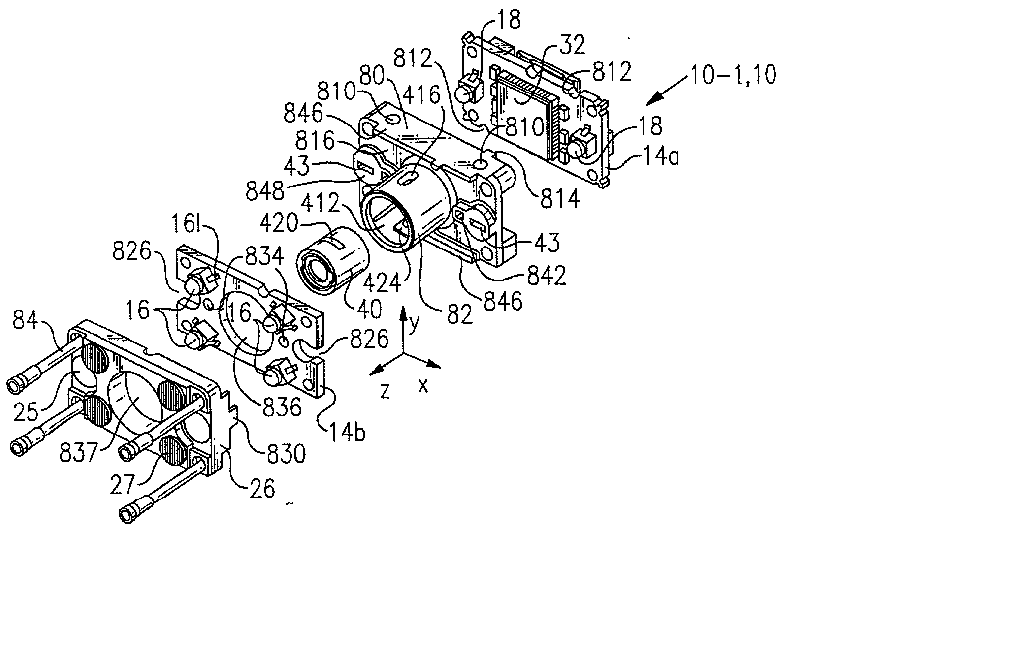
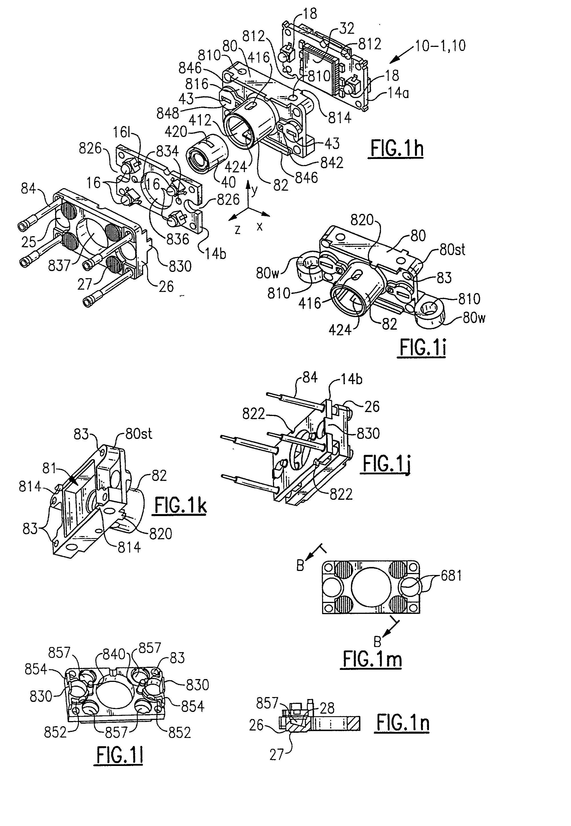
[0165] An aiming pattern generation system 685 comprising a pair of aiming LEDs 18, a pair of apertures 43, and a pair of spherical lens 25s substantially as shown in FIG. 1h is designed such that each half of the aiming pattern generating system has the properties as presented in Table 1.
1TABLE 1 Aperture size: 1.85 mm (W) .times. 0.3 mm (H) LED (18): Agilent Subminiature HLMP QM00 (690 mcd) PCB (14a) to aperture 1.07 mm (entry surface) distance: Aperture to lens member 4.1 mm light entry surface distance: Lens thickness: 1.7 mm Back focal length: 5.16 mm Front focal length: 5.16 mm Lens (25s) radius of r2 = -3 mm curvature: Lens material: Polycarbonate Paraxial magnification: -1.028
[0166] Aiming system 685 generates aiming pattern light rays substantially as is illustrated in the computer modeled side view of system 685 of FIG. 6z. It is seen that the small size of aperture 43 substantially prevents light rays from reaching borders 686 of lens 25s in the vertical plane (aiming lig...
PUM
Abstract
An imaging module in one embodiment includes an aiming system having a light source, an aperture and an optical element positioned optically forward of the aperture wherein the aiming system projects a crisp and sharp aiming pattern onto a target over a wide range of distances. In one embodiment, an aiming system is configured so that a lens operates as an aperture to project a crisp sharp aiming pattern over a wide range of distances including distances at which the aiming pattern is less than optimally focused. In another embodiment an aiming system is configured so that light emanating from a thin aperture is imaged in such manner that a crisp, sharp aiming pattern is defined over a wide range of distances. The aiming pattern in one embodiment includes sharply defined lateral edges which are useful in sighting target indicia.
Description
[0001] This application is a continuation-in-part of application Ser. No. 09 / 802,579, filed Mar. 8, 2001, entitled "Imaging Module for Optical Reader Comprising Refractive Diffuser," which is a continuation-in-part of application Ser. No. 09 / 411,936, filed Oct. 4, 1999, entitled "Imaging Module for Optical Reader." The priorities of both the Ser. Nos. 09 / 802,579 and 09 / 411,936 applications are claimed and both of the above applications are incorporated in their entireties by reference. This application is also a continuation-in-part of U.S. Ser. No. 09 / 658,811, filed Sep. 11, 2000 entitled "Optical Assembly for Barcode Scanner," which is a continuation of U.S. Ser. No. 09 / 111,476 filed Jul. 8, 1998, also entitled "Optical Assembly for Barcode Scanner," now issued as U.S. Pat. No. 6,119,939. The priorities of both the Ser. Nos. 09 / 658,811 and 09 / 111,476 applications are hereby claimed and both of the Ser. Nos. 09 / 658,811 and 09 / 111,475 applications are hereby incorporated in their en...
Claims
Application Information
Patent Timeline
Application Date:The date an application was filed.
Publication Date:The date a patent or application was officially published.
First Publication Date:The earliest publication date of a patent with the same application number.
Issue Date:Publication date of the patent grant document.
PCT Entry Date:The Entry date of PCT National Phase.
Estimated Expiry Date:The statutory expiry date of a patent right according to the Patent Law, and it is the longest term of protection that the patent right can achieve without the termination of the patent right due to other reasons(Term extension factor has been taken into account ).
Invalid Date:Actual expiry date is based on effective date or publication date of legal transaction data of invalid patent.
Inventor HUNTER, VIVIAN L.BARBER, CHARLES P.COLEMAN, ERICEHRHART, MICHAELGANNON, COLLEEN P.GARDINER, ROBERT C.HAVENS, WILLIAM H.HENNICK, ROBERT J.MCCALL, MELVIN D.RUHLMAN, THOMAS