Active optical component alignment system and method

a technology of active optical components and alignment systems, applied in the field of component alignment, can solve the problems of increasing optical insertion loss, slow method of aligning input and output ports, and progressively more complicated method of aligning optical components

Inactive Publication Date: 2005-05-24
TRZECIESKI MIKE A
View PDF1 Cites 2 Cited by
  • Summary
  • Abstract
  • Description
  • Claims
  • Application Information

AI Technical Summary

Benefits of technology

[0016]a controller circuit coupled to the photodetector for receiving the photocurrent signal, the controller circuit for providing the control signal to the actuator in dependence upon the photocurrent signal from the photodetector, where the control signal is indicative of a non-zero displacement of the first component about the point of substantial alignment within the at least a portion of the optical path.

Problems solved by technology

Upon optimizing of a single axis the procedure is repeated for all the other axes, until such a point is reached where altering the position of any axis in any direction results in the optical insertion loss to increase.
Using more than 3-axis positioners however, leads to a progressively more complicated method of aligning the optical components.
Manually moving each of these axes independently in even a dual multi-axis positioner optical set-up results in a very slow method of aligning the input and the output ports in order to minimize the optical insertion loss.
Conventional multi axis positioners used in optical alignment set-ups are made of metal, have tight springs, slow motors and are quite bulky.
Automating of these positioners with an actuating mechanism and using a control process result in optimal optical alignment, however the time required for achieving this is quite slow.
In the case where there are many optical components requiring optical alignment in the system, the process of making a decision at each increment leads to a very long time for obtaining desirable alignment.
In many cases it is quite tedious to align a multi-axis multi-component optical set-up.
Some complicated systems, for instance those used in holography set-ups, have a large number of multi-axis optical component positioning mechanisms.
This results in the optimization of only one axis at a time, where in a complicated system with many components, multi axes optimization requires a long period of time.
The controllers, actuators and optical component positioning stages are also expensive because of their high precision.

Method used


Image

  • Active optical component alignment system and method
  • Active optical component alignment system and method
  • Active optical component alignment system and method

Examples


Embodiment Construction

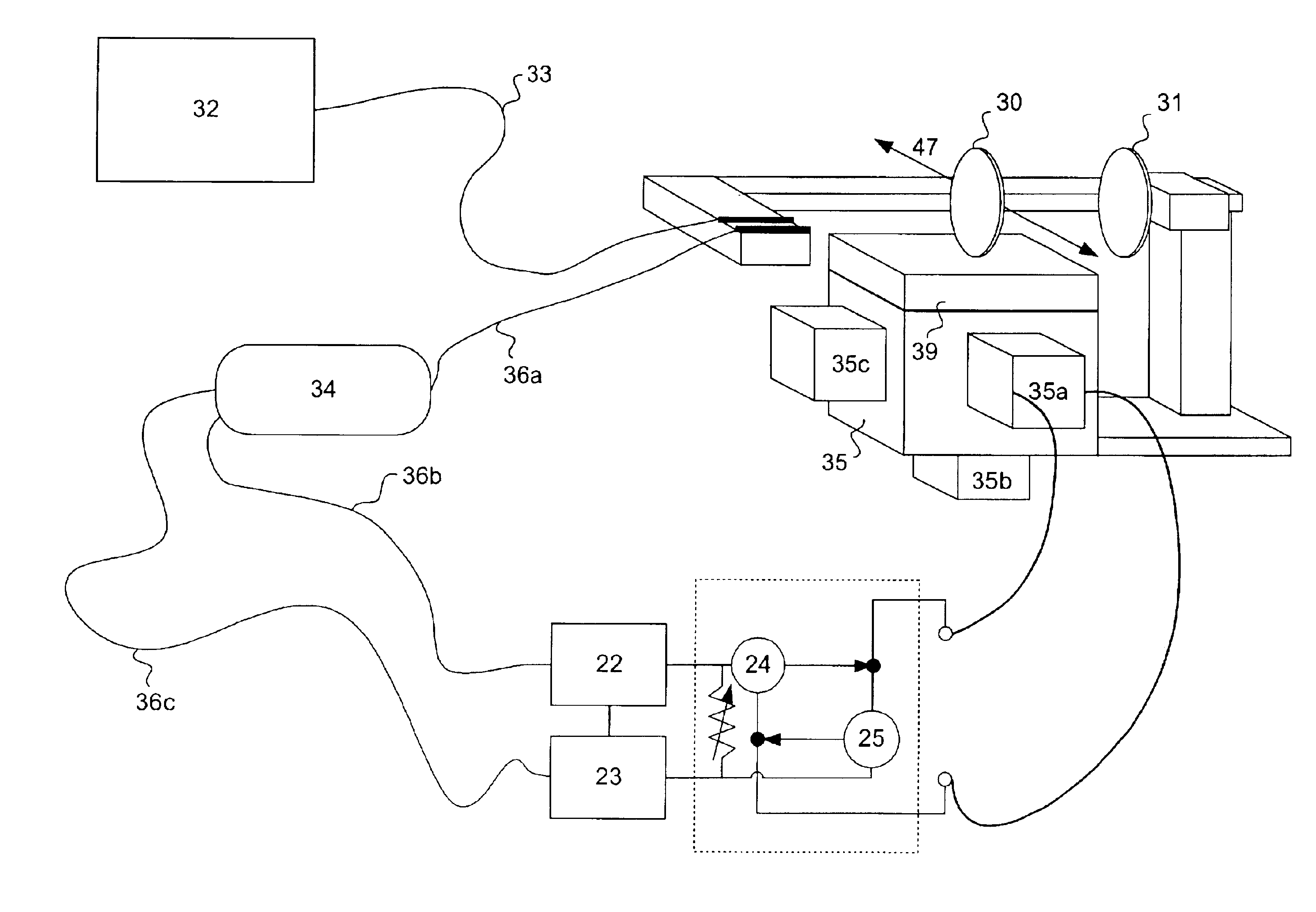
[0054]The invention overcomes the limitations of the prior art by providing an improved method of controlling an actuating mechanism for the positioning of a component within an optical alignment system.

[0055]An optical component alignment system is proposed using a “neural controller” circuit coupled to a photodetector and to an actuator mechanism, wherein an optical intensity based feedback signal is provided by the photodetector to the neural controller as feedback indicative of the relative positioning of the optical component.

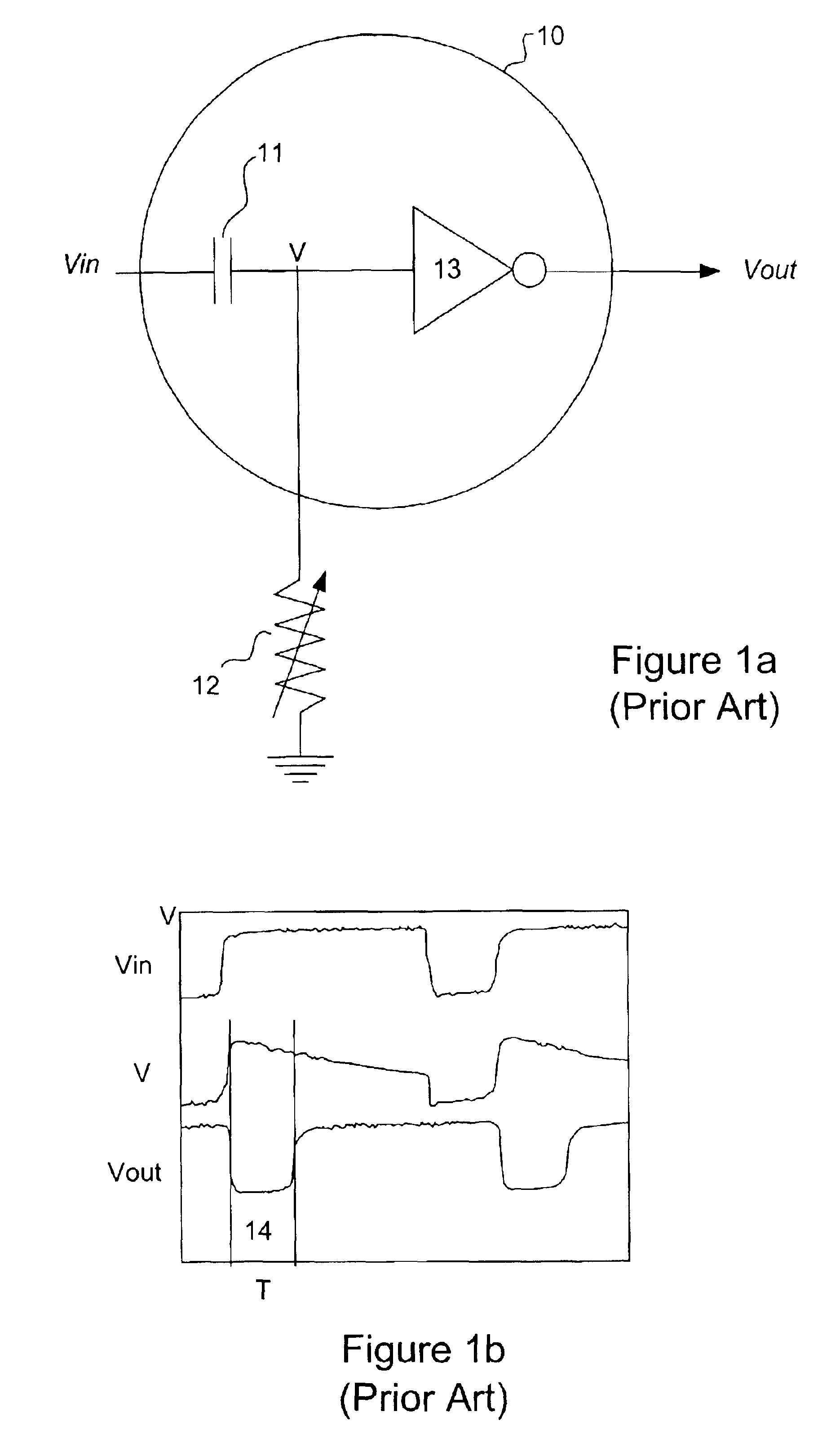
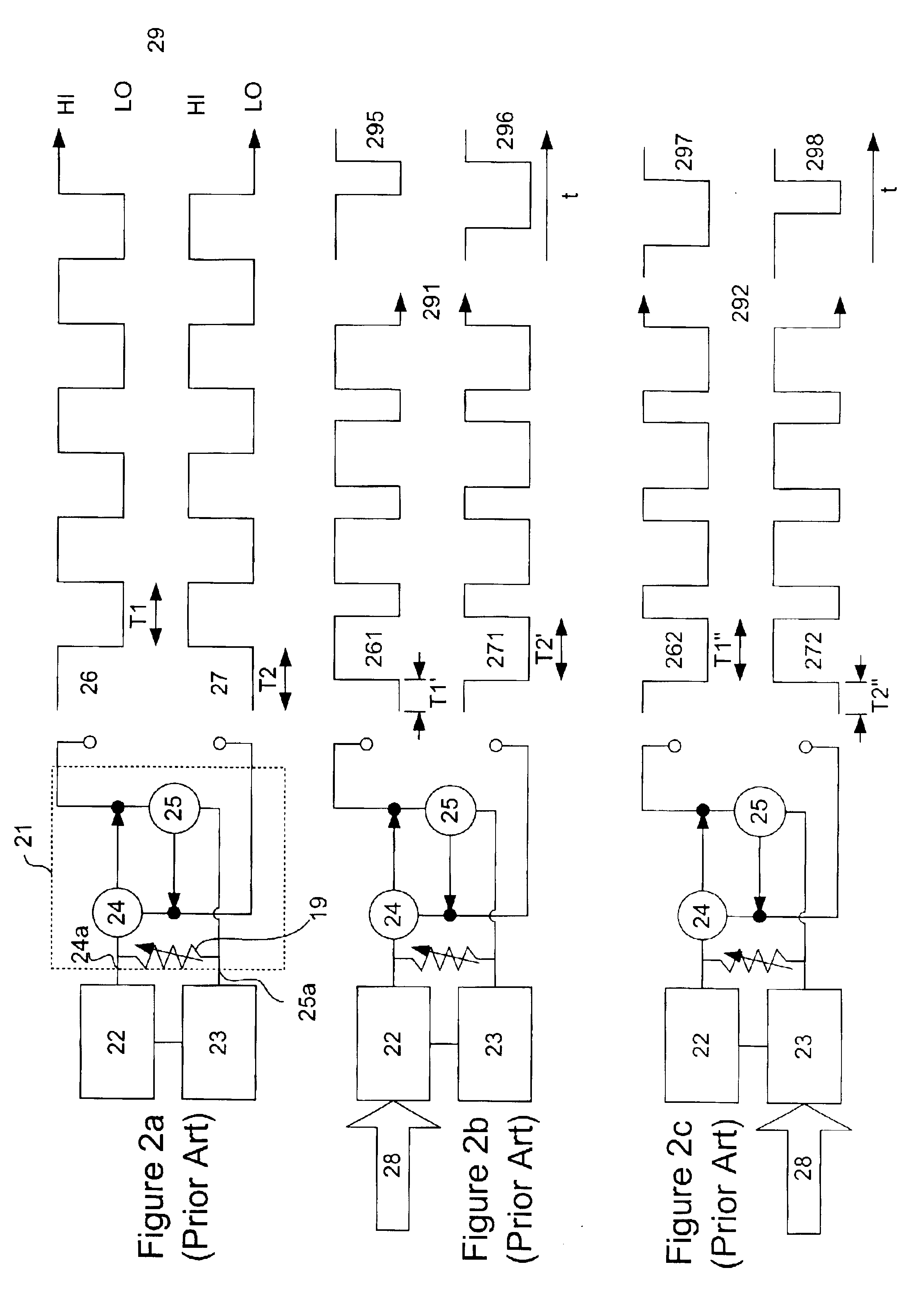
[0056]U.S. Pat. No. 5,325,031, in the name Tilden and entitled “Adaptive robotic nervous systems and control circuits therefor”, herein incorporated by reference, discloses a coupled differentiator controller circuit which exhibits characteristics of biological neurons. Configurations of this “neuron”10 are adaptable for use within a control circuit for automatically aligning optical components to a common optical signal. A figure of an examplary neuron ci...


PUM

PropertyMeasurementUnit
degrees of freedomaaaaaaaaaa
frequencyaaaaaaaaaa

Abstract

An alignment system and method is disclosed, the alignment system and method provide for alignment of at least one component to an optical signal using a neural controller circuit. The neural controller circuit facilitates parallel and sequential alignment of a plurality of components to the optical signal.

Description

FIELD OF THE INVENTION[0001]This invention relates generally to component alignment and more particularly to an apparatus for automatically aligning a plurality of components to a common optical signal.BACKGROUND OF THE INVENTION[0002]Illuminating a fiber with a laser source has enabled the size of the Internet to grow at tremendous speeds by providing for a very quick, high bandwidth, medium for communication. The basic building blocks behind the fiber optic internet are optical components, many of which use lenses, filters and various wavelength multiplexer and optomechanical components for their operation, some of which are waveguide based.[0003]For a device to be useable in an optical communication system at some point at least one fiber, usually an input fiber, must be attached to an optical component. During the assembly of these devices at some point the light coming into the device from an optical fiber must be aligned to the optics block; and the light coming out must be al...

Claims


Application Information

Patent Timeline
Patent Type & Authority Patents(United States)
IPC IPC(8): G01B11/26
CPCG01B11/26
Inventor TRZECIESKI, MIKE A.
Owner TRZECIESKI MIKE A
Why Eureka
Try Eureka