Data processing module, data processing system and data processing method

a data processing module and data processing technology, applied in the field of data processing modules, data processing systems and data processing methods, can solve the problems of limiting the mapping ratio of neural units and their synapses, waste of resources and added power consumption, and design a processing module on silicon having properties compatible with biological systems that are still far from practical with state of the art technology, so as to enable more flexibility in modifying

Pending Publication Date: 2021-10-14
GRAL MATTER LABS S AS
View PDF0 Cites 0 Cited by
  • Summary
  • Abstract
  • Description
  • Claims
  • Application Information

AI Technical Summary

Benefits of technology

[0006]It is a first object of the invention to provide a neuromorphic data processing module that enables more flexibility in modifying the number of input and output synapses of a neural units without requiring additional neural units.
[0009]According to a first aspect of the invention, an improved neuromorphic data processing module is claimed. The data processing module operates as a spiking neural network, wherein neural unit states are updated in a time-multiplexed manner. The improved data processing module comprises a combination of independently addressable memory units that determine the network topology. A first of these memory units is an input synapse memory unit which may be indexed with an input synapse identification number and provides for each identified input synapse, input synapse properties including a neural unit identification number having the identified input synapse as an input to receive firing event messages and a weight to be assigned to such messages received at that input. A second of these memory units is an output synapse memory unit which may be indexed with an output synapse identification number and provides for each identified output synapse, output synapse properties including a input synapse identification number which is a destination for a firing event messages and a delay (if any) with which such messages are to be delivered to that destination. A third of these memory units is an output synapse slice memory unit, which may be indexed with a neural unit identification number and specifies for each identified neural unit a range of indexes in the output synapse memory unit. In an embodiment the output synapse memory unit may be integrated with the input synapse memory unit as a synapse memory unit. The network topology can be flexibly reconfigured by rewriting these memory units. The fan-out range of neural units can be varied in a virtually unlimited manner, as the output synapse slice of a neural unit is defined with a single entry in the output synapse slice memory unit. The number of output synapses referred to by this entry can be 0, 1, 2 or any other number as long as the total number of all output synapses does not exceed the number of entries in the output synapse memory unit. Therewith tweaks like duplicating neural units or using relay neural units to achieve a high fan-out are obviated. Configuration of the network topology by rewriting the content of these three memory units may take place by the programmer or as part of a machine learning process, during operation.This feature also helps to exploit reduction in power consumption, since synapses are more expensive part than neural units in such systems. If for a given application there is a slack margin for performance, the mapper can utilize this flexibility to pack more networks into a smaller number of neural engines. This conversely helps to save power by putting unused data processing module in low power modes. The feature can also be exploited in plurality of other scenarios one of them being addition of debug synapses.

Problems solved by technology

However, designing a processing module on silicon having properties compatible to a biological system is still far from practical with state of the art technology, as a typical biological system typically contains billions of neurons and on average, each of those neurons has a plurality of synapses.
It is a disadvantageous of this known data processing system that it restricts the mapping ratios of neural units and their synapses.
This leads to inefficiencies in case an application neural network requires that a firing (spiking) neural unit has to transmit a firing event message to a larger number of neural units than that fixed number.
In any case it will lead to wasted resources and added power consumption.

Method used


Image

  • Data processing module, data processing system and data processing method
  • Data processing module, data processing system and data processing method
  • Data processing module, data processing system and data processing method

Examples


example i

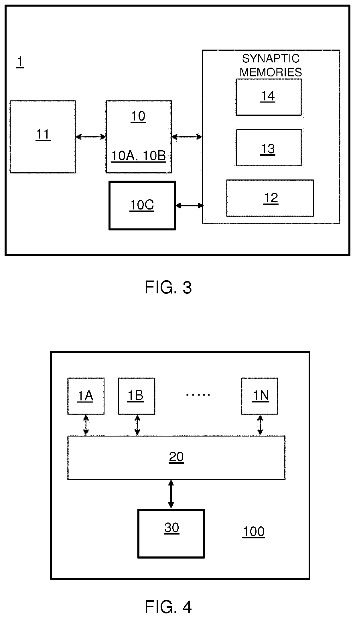
[0054]By way of example an implementation of the network of FIG. 2A is described in more detail below. It is presumed that the memory units 12, 13, 14 are loaded before with the configuration information that defines the network topology.

Input Synapse Memory Unit (14)

[0055]This memory unit 14 specifies destination information. Each entry can be considered as specifying a specific incoming synapse (input synapse) of a particular neural unit in the data processing module. This includes synapses coming from another neural in the same data processing module but may also include synapses coming from a neural unit in another data processing module arranged in a message exchange network. In an embodiment each entry of the input synapse memory unit may comprise a first field with information specifying a weight of the synapse and a second field comprising an identifier for the neural unit being the owner of the synapse.

The contents of this memory unit and the way aspects of the network topo...

example-1

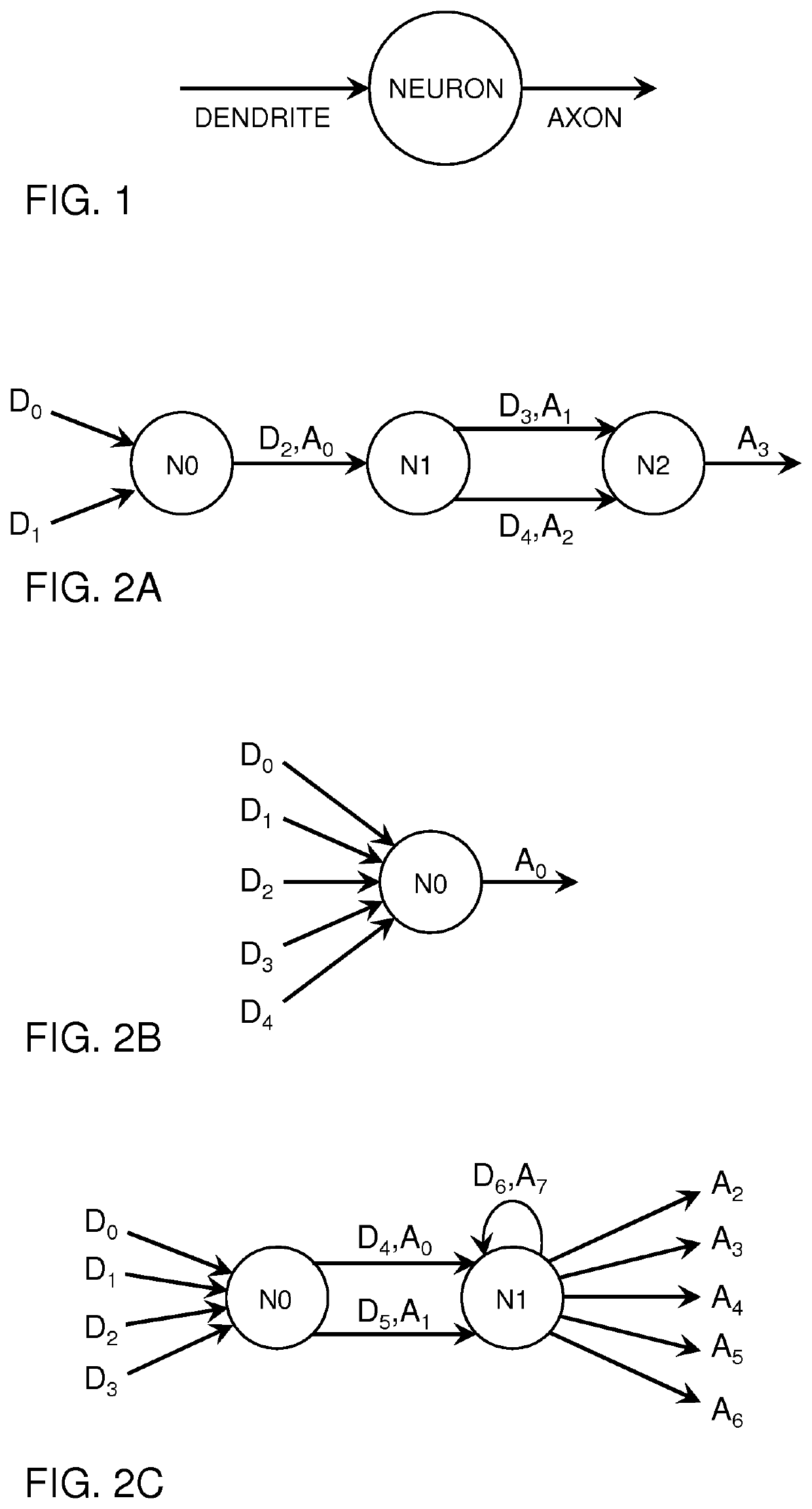
[0070]FIG. 2B shows an example data processing module with one neural unit N0, five input synapse synapses (D0, . . . , D4) and one output synapse A0. The tables below show the mapping of this example network onto the synaptic memories in the manner explained in detail in sections above. Unused locations are indicated with the symbol X.

TABLE 5Input synapse memory unit 14Input Synapse ID(Depth = 10)Neural unit IDSynaptic WeightD0N0W0D1N0W1D2N0W2D3N0W3D4N0W4XXXXXXXXX

TABLE 6Output synapse memory unit 13Output synapse ID(depth = 10)Synaptic DelayDestination IDInput synapse IDA0T0NEyDyXXXXXXXX

TABLE 7Output synapse slice memory unitNeural unit IDOffsetOutput synapse countN001XXXXXX

example-2

[0071]FIG. 2C shows an example with two neural units N0,N1, seven input synapses (D0, . . . , D6) and eight output synapses (A0, A1, . . . , A7). The tables below show the mapping of this example network onto the synaptic memories in the manner explained in detail in sections above.

TABLE 8Input synapse memory unitInput SynapseIDNeural unit IDSynaptic WeightD0N0W0D1N0W1D2N0W2D3N0W3D4N1W4D5N1W5D6N1W6XXXXXXXXX

TABLE 9Output synapse memory unitOutputSynapticDestinationInputsynapse IDDelayIDsynapse IDA0T0NExD4A1T1NExD5A2T2NEyDyaA3T3NEyDybA4T4NEyDycA5T5NEyDydA6T6NEyDyeA7T7NExD6XXXXXXXX

TABLE 10output synapse slice memory unitNeural unit IDOffsetOutput synapse countN002N126XXX


PUM


Abstract

A neuromorphic processing module (1) for time-multiplexed execution of a spiking neural network is provided that comprises a plurality of neural units. Each neural unit is capable of assuming a neural state, and has a respective addressable memory entry in a neuron state memory unit (11) for storing state information specifying its neural state. The state information for each neural unit is computed and updated in a time-multiplexed manner by a processing facility (10, neural controller) in the processing module, depending on event messages destined for said neural unit. When the processing facility computes computing that an updated neural unit assumes a firing state, it resets the updated neural unit to an initial state, accesses a respective entry for the updated neural unit in an output synapse slice memory unit, and retrieves from said respective entry an indication for a respective range of synapse indices, wherein the processing facility for each synapse index in the respective range accesses a respective entry in a synapse memory unit, retrieves from the synapse memory unit synapse property data and transmits a firing event message to each neural unit associated with said synapse property data.

Description

BACKGROUND[0001]The advent of cognitive computing has proposed neural computing as an alternative computing paradigm based on the operation of human brain. Due to their inherently parallel architecture neural computing devices are capable to mitigate the Von Neuman memory bottleneck. Inspired on biological principles, neural computing devices are designed as neural units that interact with one another through synaptic connections. Contrary to their analogically operating biological counterparts, IC implementations of these artificial neural computing devices are typically of a digital nature.[0002]This on one hand facilitates their implementation on silicon and on other hand gives the opportunity to exploit the immense technological advances that have been achieved in several decades of digital integrated circuit design. Contrary to currently available digital processing elements, biological neurons work at very low frequencies of few tens to few hundred Hz. Accordingly, this would ...

Claims


Application Information

Patent Timeline
Patent Type & Authority Applications(United States)
IPC IPC(8): G06N3/063G06N3/04
CPCG06N3/063G06N3/049
Inventor AHMED, SYED ZAHIDBORTOLOTTI, DANIELEREINAULT, JULIEN
Owner GRAL MATTER LABS S AS
Why Eureka
Try Eureka