Stent having variable properties and method of its use
What is AI technical title?
AI technical title is built by Patsnap AI team. It summarizes the technical point description of the patent document.
a stent and variable technology, applied in the field of stents for holding vessels, can solve the problems of stent end flareout affecting the stenting process, and stent end may flare outward, and the stenting process is not ideal for the larger region, so as to achieve greater force and prevent kinking of the vessel
Inactive Publication Date: 2006-06-13
BOSTON SCI SCIMED INC
View PDF63 Cites 116 Cited by
Summary
Abstract
Description
Claims
Application Information
AI Technical Summary
This helps you quickly interpret patents by identifying the three key elements:
Problems solved by technology
Method used
Benefits of technology
Benefits of technology
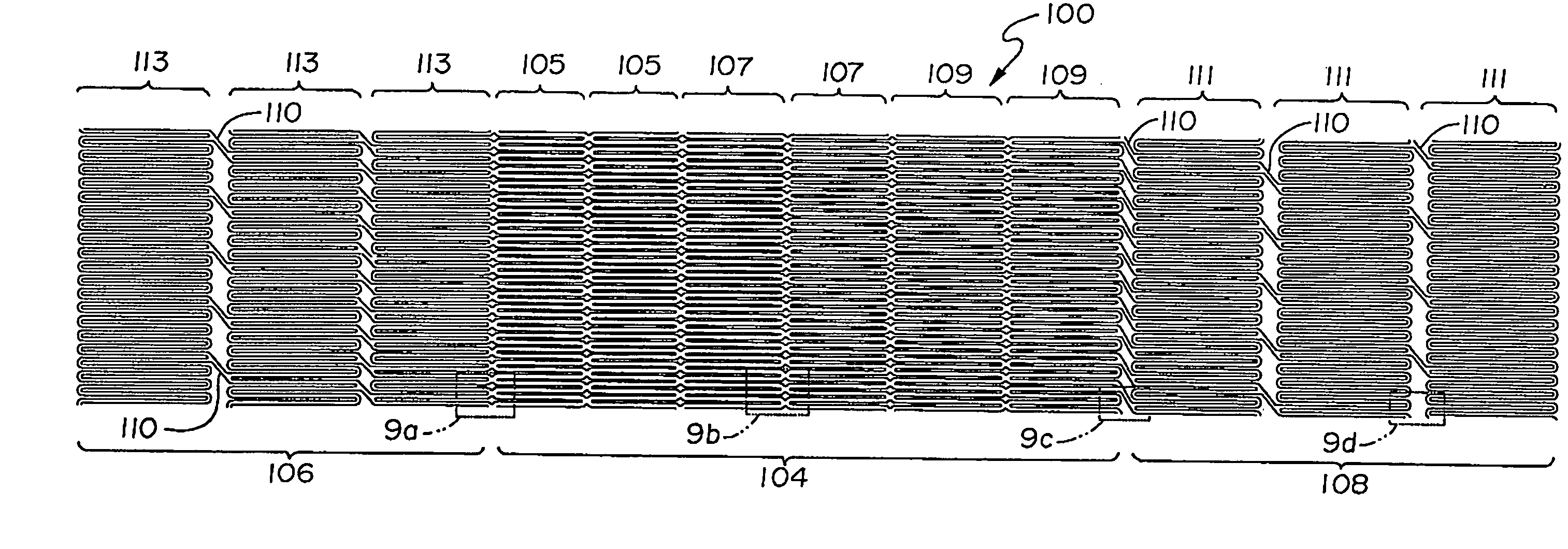
[0013]The stents of the invention may achieve a variation in radial force along their length by including in the stent structural elements which intersect at connections having more metal in regions requiring more radial force and less metal in regions requiring less radial force. The amount of intersection metal or strut member metal can be varied by varying the size of the intersection area or the size of the struts. Greater or fewer connectors actually are used to vary the flexibility along the length of the stent more than increasing radial force. In a preferred embodiment, the stent structure is formed by laser cutting a Nitinol tube, leaving a greater strut width and shorter length in regions requiring greater outward radial force and compression resistance.
[0015]The stent structure in a preferred embodiment includes a series of serpentine annular segments which are aligned to provide a tubular structure. The segments are interconnected longitudinally. A desired radial force can be varied by varying the stent strut dimensions in this and other embodiments. In one embodiment, stent regions requiring greater radial force have wider and shorter struts than regions requiring less force. The number of connectors between segments can also be varied for this purpose. It is also obtained by varying strut length and spacing and overall size. Another control is cell design per se. Closed cells provide greater plaque coverage and support than open cells. Closed cells are generally connected to cells in adjoining segments of the stent whereas open cells are not so connected. These factors also provide control over properties such as flexibility and conformability. Cell geometry, i.e., closed and open, is used to provide good plaque support in the region of the stenoses (closed) and less support (open) and more flexibility to either side of the stenoses. Also, closed cell structure may be used to bridge the origin of the external carotid artery or any other vessel side branch opening.
[0017]Stents made in accordance with the present invention can provide an outward radial force more closely matching the local force requirements in a tapered vessel. In particular, the stents provide greater force only where required at a stenosis, without providing too much force in the region of healthy tissue. The stents provide an expanded geometry more closely tailored to the requirements of a tapering vessel region. They are preferably stiff and strong at the proximal large diameter end or middle and weak and more flexible at the distal smaller diameter end to provide strain relief and prevent kinking of the vessel distal to the stent. The proximal end may also be flexible.
Problems solved by technology
In the region of the carotid bulb and the ostium of the internal carotid artery, stenoses present a particular problem for carotid stenting due to the large tapering of the vessel interior from the common carotid artery (both the left and the right) to the internal carotid artery.
The stent end may thus flare outward, protruding into, and possibly irritating non-stenosed tissue.
If this force is properly matched for the smaller vessel region, it is likely less than optimal for the larger region.
Method used
Image
Click on the blue label to locate the original text in one second.
Reading with bidirectional positioning of images and text.
Examples
Embodiment Construction
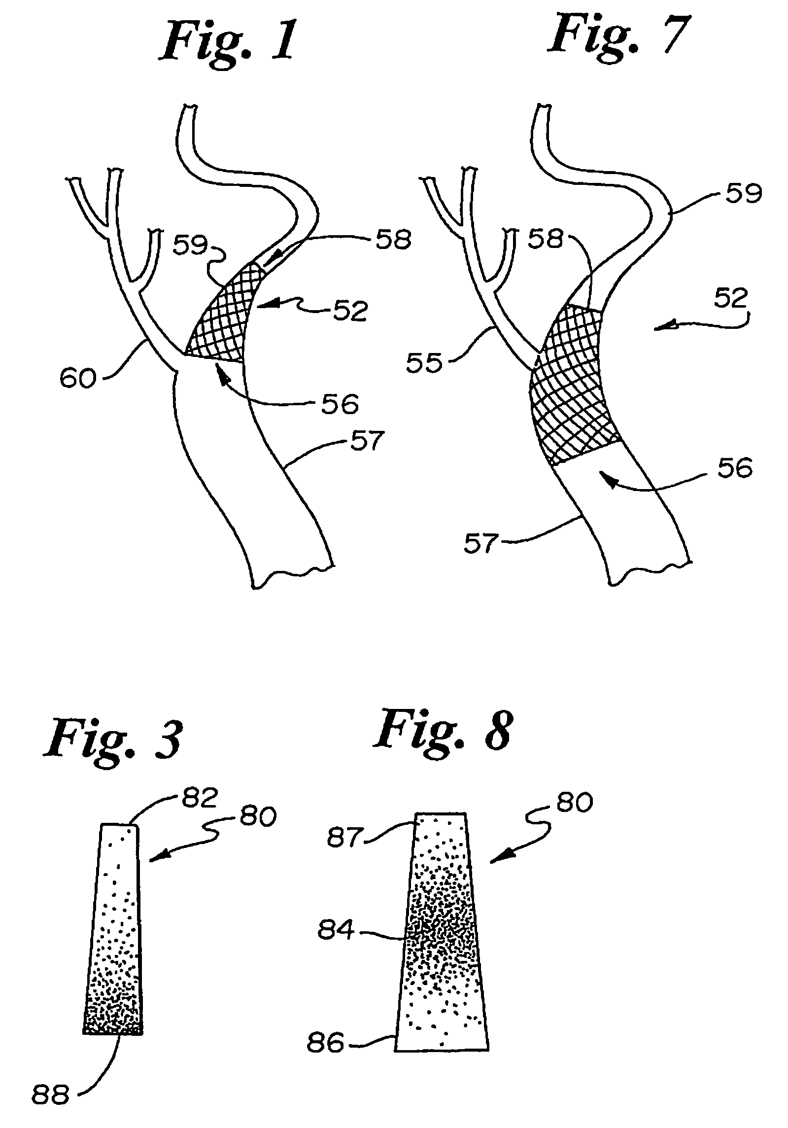
[0031]FIG. 1 illustrates a narrowing vessel 52, such as the internal carotid artery, having a wide region 56, a narrowed region 58, and a stenosis (not shown) somewhere in between, i.e., in the cross-hatched region. The narrowing vessel of FIG. 1 illustrates the geometry as found in an ostium at the bifurcation of the left common carotid 57, where blood flows from the left common carotid artery 57 into the left internal carotid artery 59. The bifurcation also opens into the left external carotid artery 60. An ordinary stent with sufficient force to hold open the wide region 56 would have greater force than necessary to hold open the narrowed region 58.
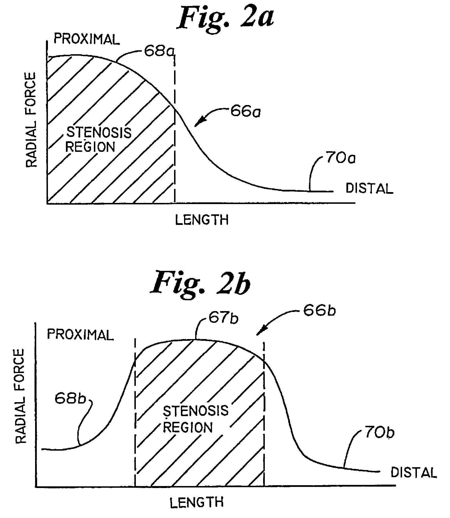
[0032]FIG. 2a illustrates a plot 66a of outward radial force F along a tapered, expanded stent length L for a stent embodying the present invention. The stent has a greater force in end region 68a than at the opposite end region 70a. A tapered stent having the force curve of FIG. 2a is suitable for bridging a stenosis as illustrated in...
PUM
Abstract
A stent and method of its use, the stent in its expanded configuration, exhibiting varying outward radial force along its length. In use, the expanded stent is of a tapered configuration which provides greater force in vessel regions requiring greater force and less force in regions requiring less. In particular the stent is useful in the ostium regions and at areas of bifurcation in vessels. Varying force over the length of the stent is achieved by varying the number of elements, the density of elements, the thickness of the elements making up the stent body, and maintaining a substantially metal to artery ratio in the expanded stent over its length.
Description
CROSS REFERENCE TO CO-PENDING APPLICATION[0001]This application is a Continuation application of U.S. application Ser. No. 10 / 301,983, filed Nov. 22, 2002, now U.S. Pat. No. 6,669,723 which is a continuation of U.S. application Ser. No. 09 / 735,398, filed Dec. 12, 2000, now U.S. Pat. No. 6,485,509 B2, issued Nov. 26, 2002, which is a continuation of U.S. application Ser. No. 09 / 314,658, filed May 19, 1999, now U.S. Pat. No. 6,159,238, issued Dec. 12, 2000 which is a divisional of U.S. application Ser. No. 09 / 034,249, filed Mar. 4, 1998, now U.S. Pat. No. 5,938,697, issued Aug. 17, 1999, which are incorporated herein in their entirety by reference.FIELD OF THE INVENTION[0002]The invention relates generally to medical devices and their use. More specifically, the invention relates to stents for holding vessels such as arteries open to flow, particularly in the regions of bifurcations.BACKGROUND OF THE INVENTION[0003]Stents are radially expandable endoprostheses which are typically intr...
Claims
Application Information
Patent Timeline
Application Date:The date an application was filed.
Publication Date:The date a patent or application was officially published.
First Publication Date:The earliest publication date of a patent with the same application number.
Issue Date:Publication date of the patent grant document.
PCT Entry Date:The Entry date of PCT National Phase.
Estimated Expiry Date:The statutory expiry date of a patent right according to the Patent Law, and it is the longest term of protection that the patent right can achieve without the termination of the patent right due to other reasons(Term extension factor has been taken into account ).
Invalid Date:Actual expiry date is based on effective date or publication date of legal transaction data of invalid patent.

