Screw anchor with conical head for rail attachment

a technology of conical head and screw, which is applied in the direction of screws, threaded fasteners, ways, etc., can solve the problem of not being able to transmit sufficiently high lateral forces

a technology of conical head and screw, which is applied in the direction of screws, threaded fasteners, ways, etc., can solve the problem of not being able to transmit sufficiently high lateral forces

US20110262241A1Inactive Publication Date: 2011-10-27VOSSLOH WERKE GMBH

Image

  • Screw anchor with conical head for rail attachment
  • Screw anchor with conical head for rail attachment
  • Screw anchor with conical head for rail attachment

Examples


Embodiment Construction

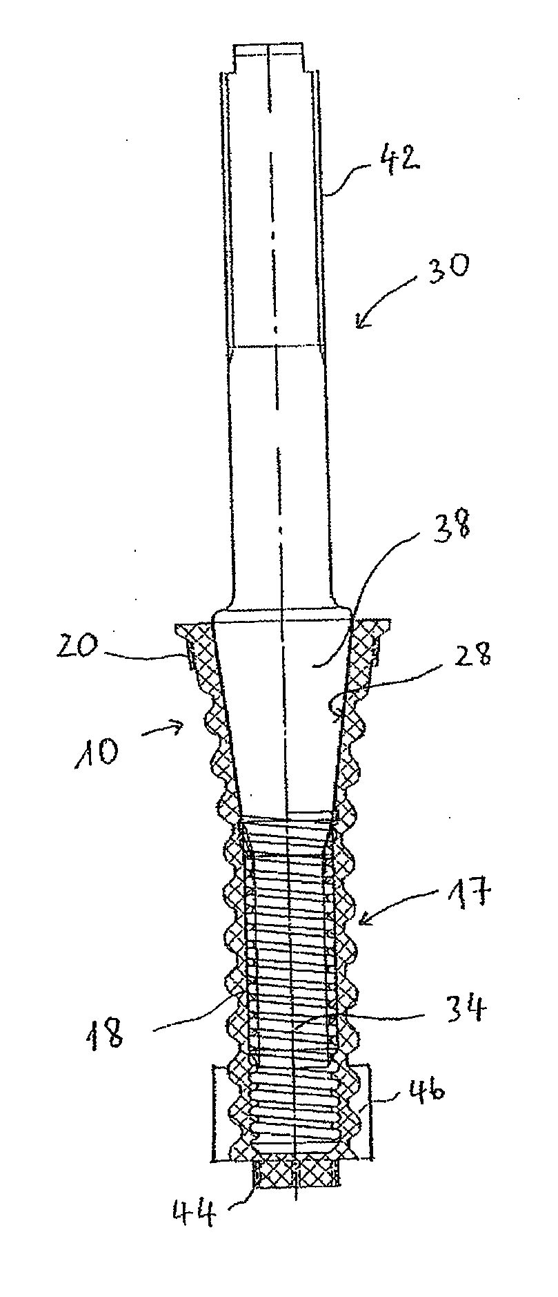
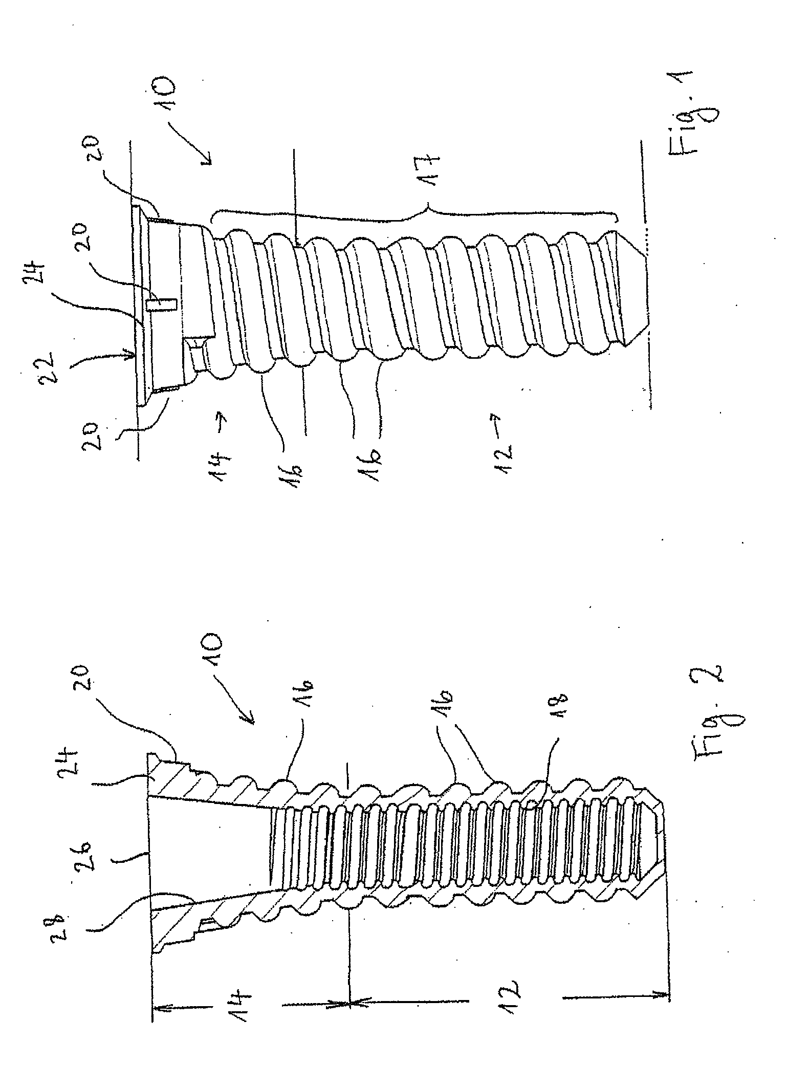
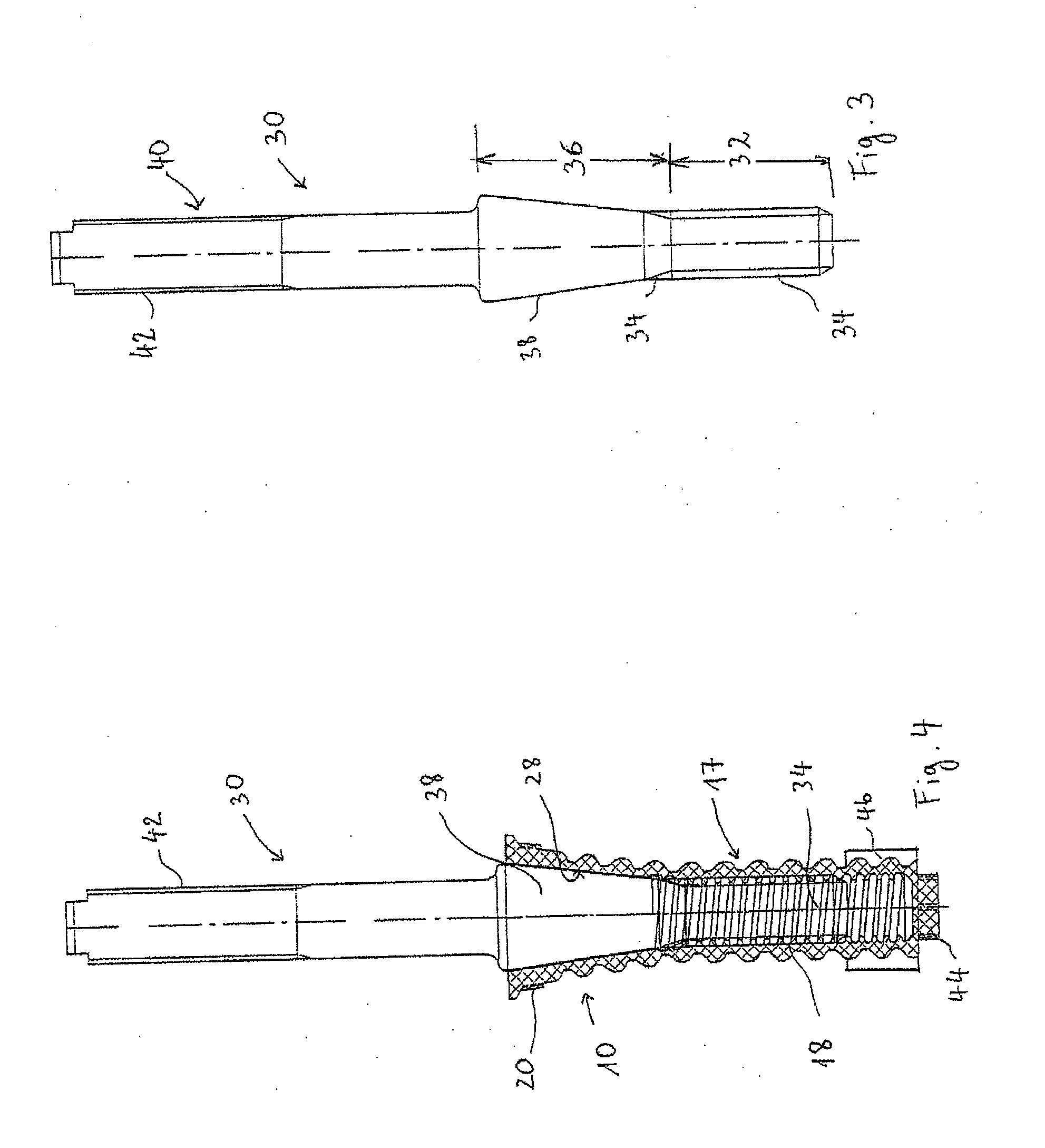
[0004]The object forming the basis of the invention is to propose a screw anchor for concrete attachment to a railroad tie or solid track which can transmit increased lateral forces from the track fastening into the railroad tie or solid track. This object is achieved by a screw anchor having the features of claim 1. Preferred embodiments of the invention follow from the other claims.

[0005]According to the invention a screw anchor for concrete attachment to a railroad tie or solid track and for force-fitted connecting to a fastening element comprises external threads disposed on the exterior of the screw anchor and internal threads disposed inside the screw anchor. The screw anchor is characterized in that the latter comprises two sections adjacent to one another in the longitudinal direction, a first section having a substantially cylindrical external shape, and a second section having a substantially conical external shape. The second section is disposed here between the first sec...


PUM


Abstract

A screw anchor for concrete attachment to a railroad tie or solid track comprises external threads (16) disposed on the exterior of the screw anchor (10) and internal threads (18) disposed inside the screw anchor (10) for force-fitted connecting to a fastening element (30), wherein the screw anchor (10) comprises two sections (12, 14) adjacent to one another in the longitudinal direction, the first section (12) having a substantially cylindrical external shape and the second section (14) having a substantially conical external shape, and wherein the second section (14) is disposed between the first section (12) and an inlet opening (26) for the fastening element (30).

Description

FIELD OF THE INVENTION[0001]The invention relates to a screw anchor according to the preamble to claim 1 for concrete attachment to a solid track or railroad tie and for force-fitted connecting to a fastening element. The invention further relates to this type of screw anchor with a screwed-in fastening element and a solid track or railroad tie with at least one screw anchor according to the invention.PRIOR ART[0002]Screw anchors for concrete attachment to a solid track or railroad tie are used in railway construction to connect a rail and a substructure in the form of a tie or a solid track. Here the rail is fastened to the substructure by means of tie screws. Screw anchors are generally made of plastic and can be cast integrally with a concrete tie or solid track when the latter is being produced. A further reason for providing a plastic anchor is that the tie screw should be electrically isolated from the tie or the solid track.[0003]The disadvantage of conventional screw anchors...

Claims


Application Information

Patent Timeline
27 Oct 2011
Publication
US20110262241A1
IPC
F16B13/06
CPC
E01B9/18; F16B37/125; F16B35/041; F16B3/06
Inventors
BOSTERLING, WINFRIED; HUNOLD, ANDRE