Re-tightenable stator body wedge system

a stator body and wedge technology, applied in the direction of dynamo-electric machines, electrical equipment, magnetic circuit shapes/forms/construction, etc., can solve the problems of loss of radial force on the armature bars, and achieve the effect of shortening outage cycles and simplifying inspection processes

Inactive Publication Date: 2006-12-26
GENERAL ELECTRIC CO
View PDF11 Cites 6 Cited by
  • Summary
  • Abstract
  • Description
  • Claims
  • Application Information

AI Technical Summary

Benefits of technology

[0006]The present invention provides a means by which the radial force on the armature bars of a generator may be restored by adjusting the position of the slide under the wedge, without removing the rotor. This permits reusing and extending the life of the original wedging system components, simplifying inspection processes and shortening outage cycles.
[0007]More specifically, the present invention relates to a redesign of the slide component to incorporate lateral locking features, as well as a redesign of the wedge component to accommodate a tool for retightening the slide component. In the exemplary embodiment, each lateral side of the slide component is formed with a defined number of discrete fingers or “herringbones” cut at a prescribed angle, with the herringbones slanted inwardly from their outer edges toward the longitudinal center axis of the slide in the direction in which the slide is to be driven. The angle of the herringbones and the cut width or slots between the herringbones may vary for specific applications. In addition, the cross-sectional width of the slide area containing the herringbones is wider than the remainder of the slide, allowing for this section of the slide to flex and engage the side walls of the stator slot. This contact provides an additional frictional force over and above the frictional force between the slide and wedge mating surfaces. More specifically, given the angled orientation of the herringbones, and their inherent flexibility, lateral forces are developed against the side walls of the stator slots, and it is this frictional force of the herringbones against the stator slot walls that prevents reverse displacement of the slide that would otherwise result in a loss of radial force on the armature bars.
[0008]The redesigned slides are also shorter in length than the associated wedges in order to permit axial adjustment during retightening that restores the radial force, thus compensating for the effects of load relaxing that occur over time.
[0009]Retightening can be done with the rotor in situ by using a specially designed tool for driving the slides under the associated wedges. This tool may be anchored through a hole in the top of the wedge component, and a push-arm located in a cut-out at the end of the wedge component, enabling engagement with the end of the next adjacent slide. The push-arm is able to drive the slide axially forward to increase the radial force on the wedge and slot components. By being able to reach the slide with this tool, one can just retighten the wedge or wedges that need to be retightened, whether the wedge is an end wedge or a wedge spaced axially inwardly of the end wedge.

Problems solved by technology

More specifically, given the angled orientation of the herringbones, and their inherent flexibility, lateral forces are developed against the side walls of the stator slots, and it is this frictional force of the herringbones against the stator slot walls that prevents reverse displacement of the slide that would otherwise result in a loss of radial force on the armature bars.

Method used


Image

  • Re-tightenable stator body wedge system
  • Re-tightenable stator body wedge system
  • Re-tightenable stator body wedge system

Examples


Embodiment Construction

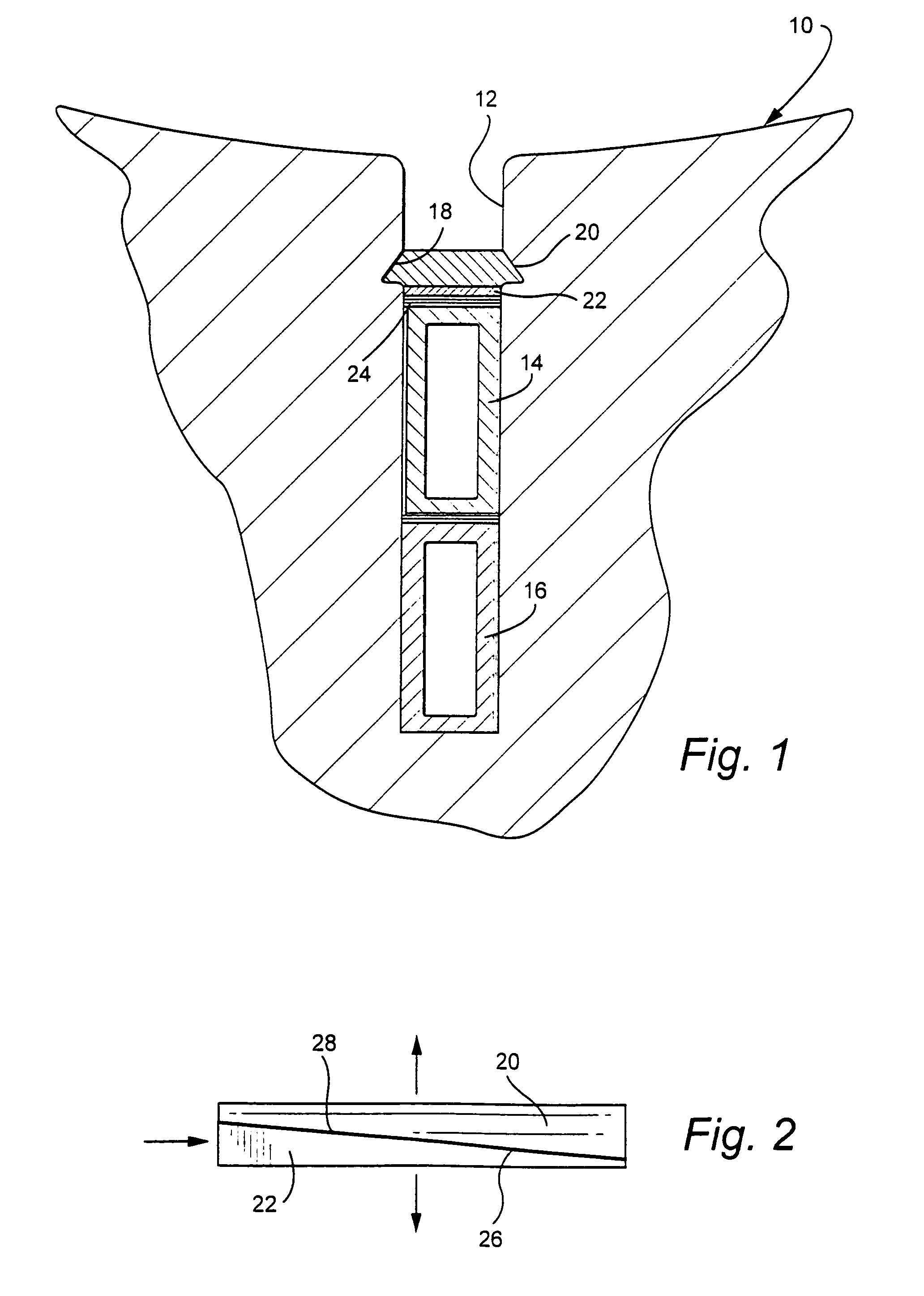
[0020]Referring initially to FIG. 1, the generator stator core is partially shown at 10, it being understood that the core includes a plurality of radial slots 12 which extend axially along the core and which receive stator windings 14, 16. Each slot 12 is formed adjacent its mouth with dovetail grooves or undercuts 18 permitting wedge and slide components 20, 22 to be inserted in an axial direction within a slot. If needed, one or more filler strips 24 may be inserted in conventional fashion between the winding 14 and slide 22. Note that, relative to the slot 12, the slide 30 is radially inward of the wedge 48.

[0021]FIG. 2 illustrates the manner in which flat sloped surface 26, 28 on conventional wedge and slide components 20, 22 cooperate to apply radial force on the stator bars as the slide component is driven under the wedge in a conventional stator winding wedge system.

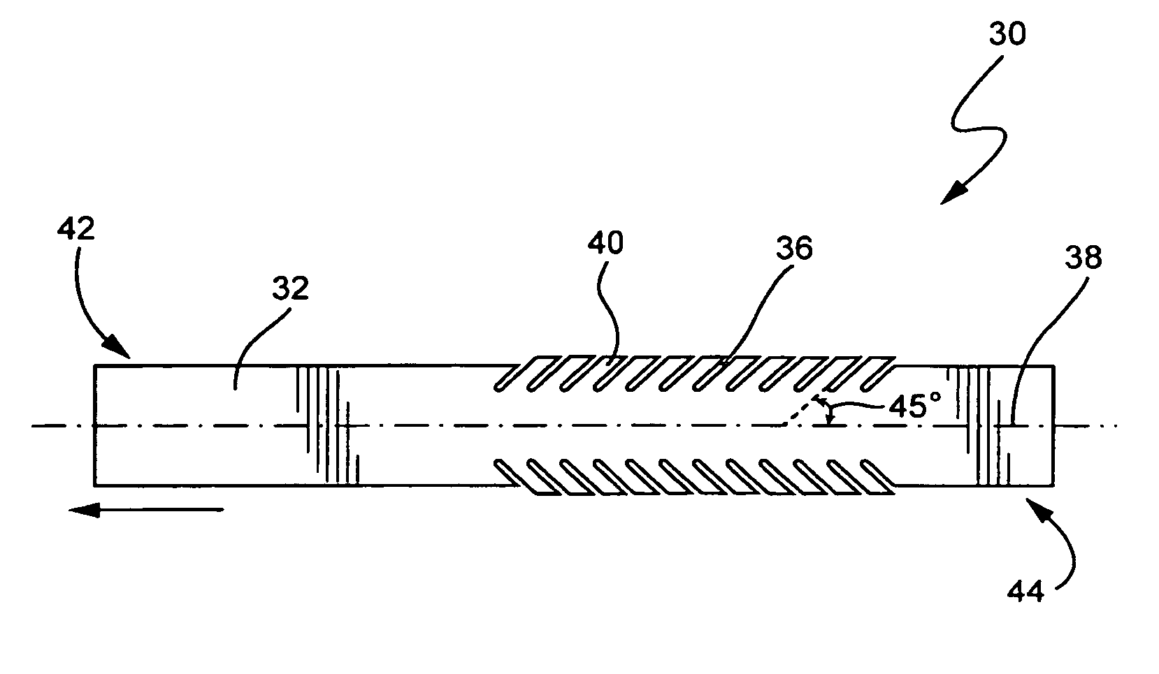
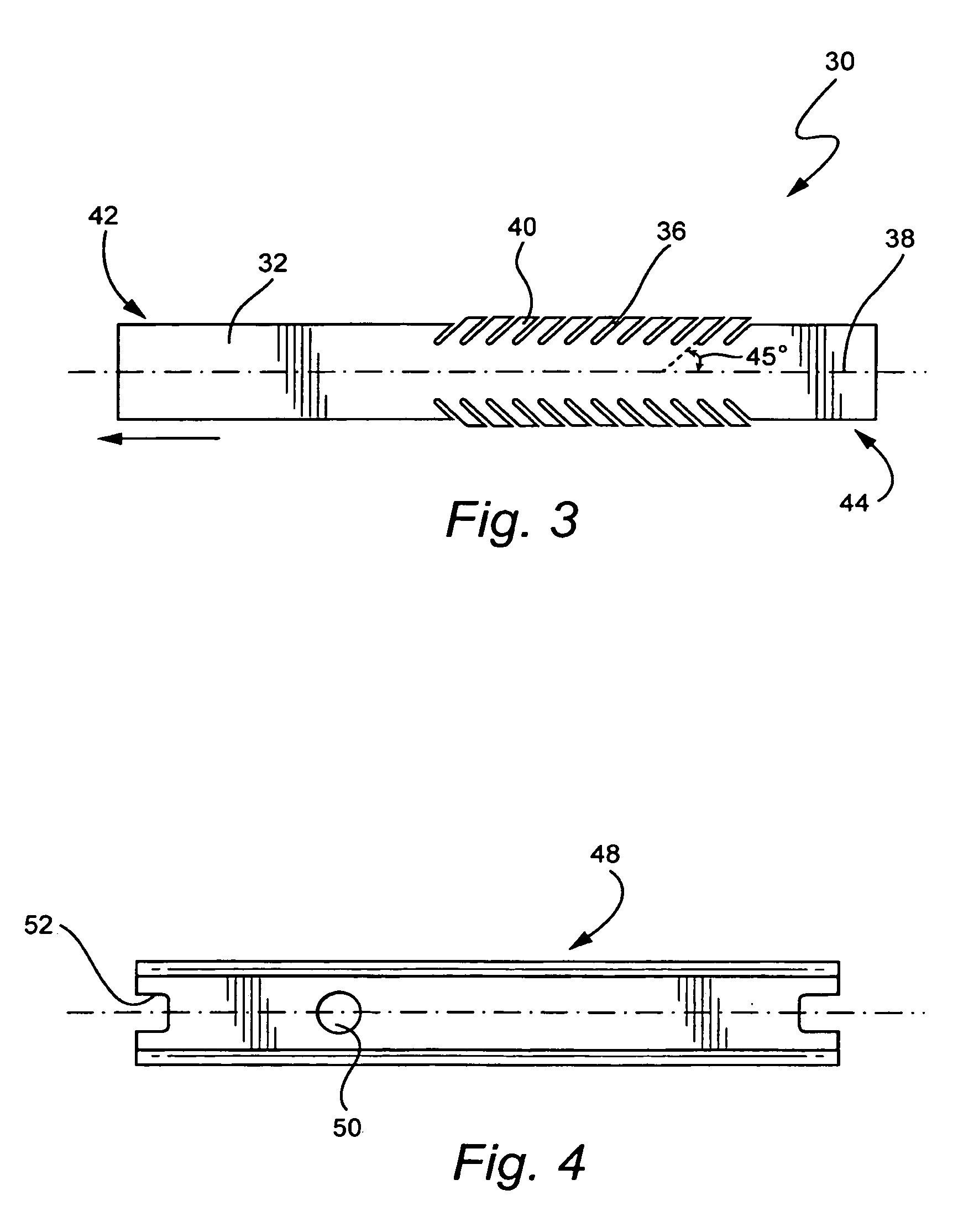
[0022]Turning to FIG. 3, the new slide component 30 in accordance with an exemplary embodiment of this inventi...


PUM


Abstract

A generator stator core has a plurality of axially extending radial slots arranged about the periphery thereof with windings in each of the radial slots. At least one adjustable wedge and slide assembly is located in each of the slots, arranged to restrain the windings, the assembly including a wedge component and a slide component which interface along respective sloped surfaces formed on respective sides of each of the wedge component and the slide component. The slide component is formed with a zone of laterally extending, discrete fingers on each side thereof that are angled relative to a longitudinal axis of the slide. The wedge component is slidably received in a pair of dovetail grooves in the radial slot with the slide component located between the wedge component and the windings such that the discrete fingers engage side walls of the radial slot.

Description

BACKGROUND OF THE INVENTION[0001]This invention relates to dynamoelectric machines generally, and, more specifically, to a new tapered slide component in a stator slot wedging system used to secure an armature winding in medium and large generators.[0002]Stator winding wedge systems are designed to maintain radial pressure on the armature bars and slot components of a generator to thereby prevent the damaging effects of electromagnetic vibration forces. As the generator operates, load induced compressive creep and slot component material shrinkage cause a reduction in the radial force, which eventually results in a detectable loose wedge condition. Currently, when the wedging system of a generator becomes loose after operation for some time, the generator must be re-wedged. The present re-wedging process involves rotor removal and also removal of all of the old wedging material and subsequent replacement with new components.[0003]This problem has been addressed previously in prior U...

Claims


Application Information

Patent Timeline
Patent Type & Authority Patents(United States)
IPC IPC(8): H02K3/48
CPCH02K3/487H02K15/024
Inventor YUNG, MABEL SHANGBLAKELOCK, THOMAS RICHARDIVERSEN, ALAN MICHAELSALEM, SAMEHBUTMAN, JR., THOMAS RUFUSBREITENSTEIN, ADRIAN
Owner GENERAL ELECTRIC CO
Why Eureka
Try Eureka