Assembly for an electric machine, method for producing an assembly and electric machine having an assembly

a technology of assembly and electric machine, which is applied in the direction of magnetic circuit rotating parts, soldering apparatus, magnetic circuit shape/form/construction, etc., can solve the problems of high operating temperature, relatively expensive and/or difficult processing, and achieve high rotational speed, high temperature during operation, and high radial force

a technology of assembly and electric machine, which is applied in the direction of magnetic circuit rotating parts, soldering apparatus, magnetic circuit shape/form/construction, etc., can solve the problems of high operating temperature, relatively expensive and/or difficult processing, and achieve high rotational speed, high temperature during operation, and high radial force

US20160241096A1Inactive Publication Date: 2016-08-18ROBERT BOSCH GMBH

Image

  • Assembly for an electric machine, method for producing an assembly and electric machine having an assembly
  • Assembly for an electric machine, method for producing an assembly and electric machine having an assembly

Examples


Embodiment Construction

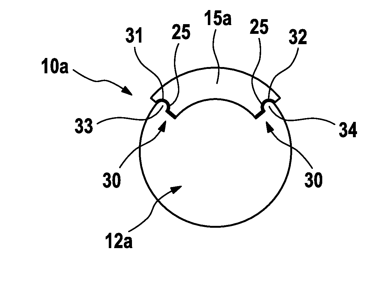
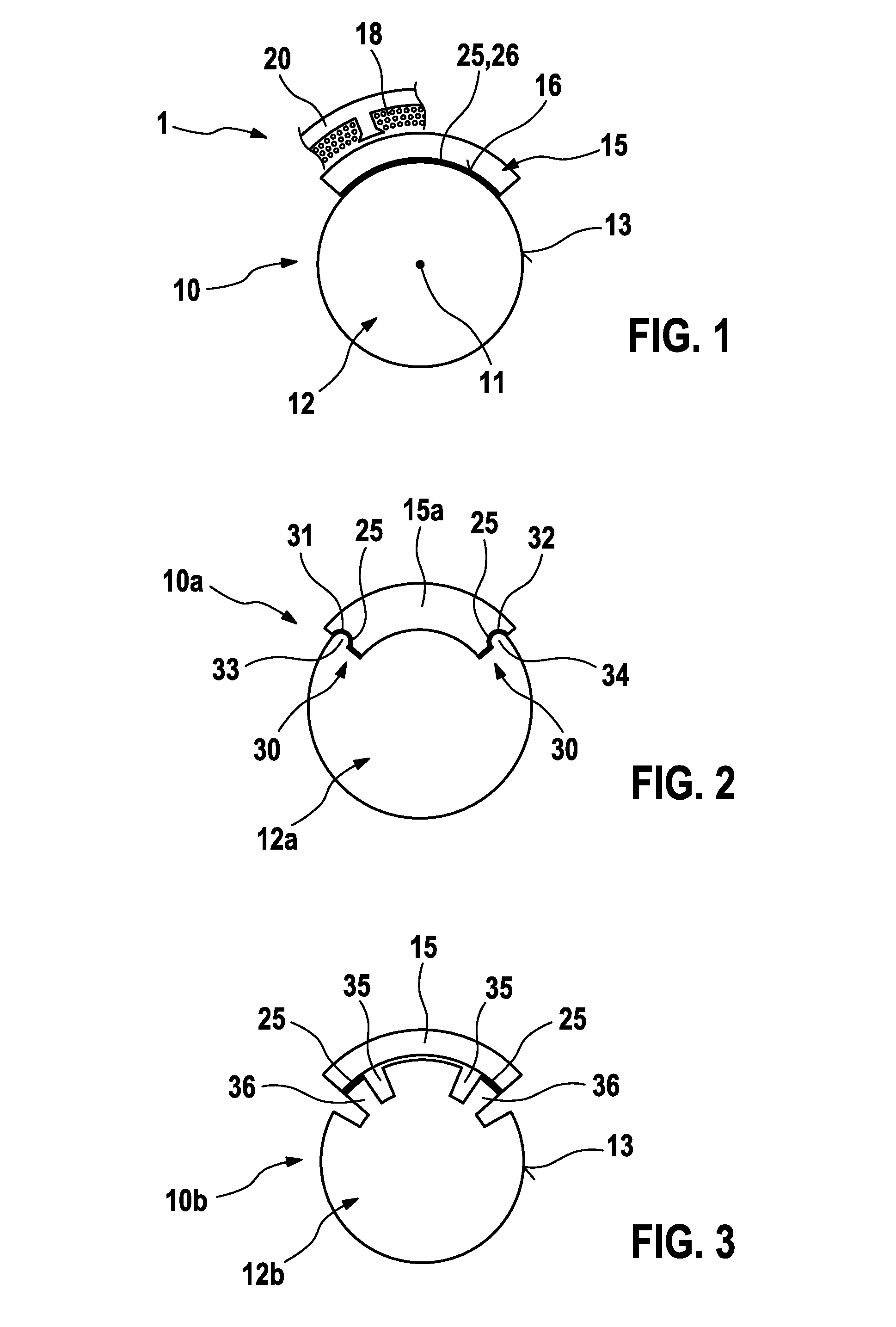
[0021]In FIG. 1, a first inventive assembly 10 for an electric machine 1 is depicted in a highly simplified manner. The machine 1 relates particularly to an electric motor as a constituent part of a servo drive in a motor vehicle, such as a seat adjustment drive, a power window drive, a sunroof drive or something similar. The invention should, however, not be limited to such applications of an assembly 10.

[0022]The assembly 10 comprises a rotor 12, which is rotatably mounted about an axis of rotation 11 and which in practice typically consists of a multiplicity of sheet metal elements which are stacked vertically on top of one another in the plane of the drawing of FIG. 1. Said sheet metal elements are rotatably mounted about an axis (not depicted) which simultaneously forms the axis of rotation. In the ideal case, the rotor 12 has a peripheral surface 13 which is formed in a circular cylindrical manner and on which a plurality of, at least two-in practice however, for example, four...


PUM

PropertyMeasurementUnit
shapeaaaaaaaaaa
demagnetization temperatureaaaaaaaaaa
currentaaaaaaaaaa

Abstract

The invention concerns an assembly (10; 10a ; 10b) for an electric machine (1), comprising a rotor (12; 12a; 12b) which is rotatable in a rotational shaft (11) and magnet elements (15; 15a) which are disposed on the periphery of the rotor (12; 12a; 12b) and are connected thereto. According to the invention, the connection between the rotor (12; 12a; 12b) and the magnet elements (15; 15a) takes the form of a solder connection (25).

Description

BACKGROUND OF THE INVENTION[0001]The invention relates to an assembly for an electric machine. The invention furthermore relates to a method for producing an assembly according to the invention as well as to and electric machine and to the application of said inventive assembly.[0002]An assembly for an electric machine is already known from the technical field. This assembly is, for example, a constituent part of an electric motor, in which permanent magnet elements are disposed on the periphery of a rotatably mounted rotor, wherein the permanent magnet elements, referred to below simply as magnet elements, interact with fixed wire-wound coils which are disposed particularly in the region of a pole housing and through which current can be passed. Such magnet elements are attached to the periphery of the rotor in practice by means of adhesive bonding, bandaging or by means of a positive-locking connection between the magnet elements and the rotor. In addition, the process is known fo...

Claims


Application Information

Patent Timeline
18 Aug 2016
Publication
US20160241096A1
IPC
H02K1/28; H02K1/27
CPC
H02K1/278; H02K1/274; H02K1/28; B23K1/0008; H02K15/00
Inventors
MUELLER, TANKRED