Adaptive braking and directional control system (abadcs)

A directional control and steering system technology, applied in the field of braking and steering response systems, which can solve the problem that wheel and rudder steering cannot respond quickly to control input

Pending Publication Date: 2021-04-02
EAGLE AEROSPACE LTD
View PDF0 Cites 0 Cited by
  • Summary
  • Abstract
  • Description
  • Claims
  • Application Information

AI Technical Summary

Problems solved by technology

As a result, wheel and rudder steering may not respond as quickly to operator control inputs as ABS and ASBS may cause or allow sticky skid from the vehicle's tires

Method used


Image

  • Adaptive braking and directional control system (abadcs)
  • Adaptive braking and directional control system (abadcs)
  • Adaptive braking and directional control system (abadcs)

Examples


Embodiment Construction

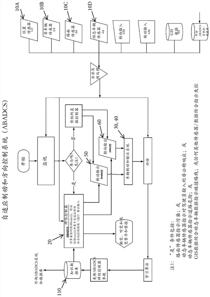
[0033] Referring now to the accompanying drawings, figure 1 A flowchart is shown showing the steps of operation of an adaptive braking and directional control system (ABADCS) for a vehicle according to the present invention. Typically, the system is initiated by a monitoring step in which a plurality of sensors 10A-D (see figure 2 ) The signal provided by a neural controller 20 (see figure 2 ) monitoring.

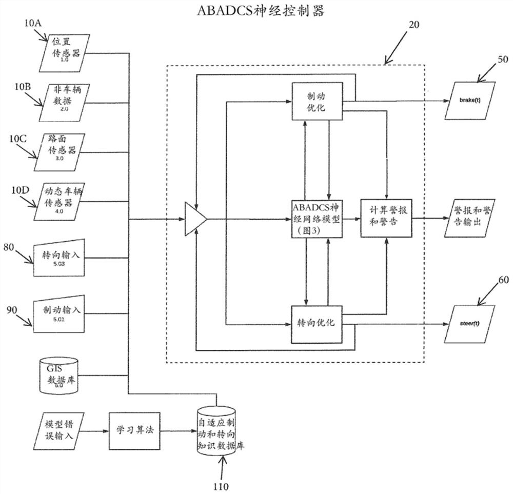
[0034] refer to figure 2, the plurality of sensors may include a position sensor 10A, a non-vehicle sensor 10B, a road surface sensor 10C, and a dynamic vehicle sensor 10D. The location sensor 10A may be configured to provide real-time location data of the vehicle, such as latitude, longitude, altitude, and the like. It is contemplated that such a position sensor 10A may be arranged to provide a signal indicative of the three-dimensional position of the vehicle (eg, from a global positioning system (GPS)) or the like.

[0035] Non-vehicle sensors 10B may be provide...


PUM


Abstract

The present invention relates to a method of controlling and optimizing braking and directional control of a vehicle operated on a contaminated, compliant, or non-compliant surface. The method includes steps of collecting data from a plurality of sensors, the data being indicative of a condition of the contaminated, compliant, or non-compliant surface; sending the data to a neural controller having an algorithm configured to process the data. The algorithm includes determining optimum braking and directional control instructions for the vehicle, generating warnings and alerts based on the calculated optimum braking and directional control instructions, and sending the optimum braking and directional control instructions to a braking and steering system of the vehicle and the warnings and alerts to an alert and warning system of the vehicle. The method further includes adjusting the steering and directional control of the braking and steering system in accordance with the optimum braking and directional control instructions provided by the neural controller.

Description

[0001] Cross References to Related Applications [0002] This application claims the benefit of U.S. Provisional Patent Application No. 62 / 694,719, filed July 6, 2018, which is incorporated by reference in its entirety. technical field [0003] The present invention relates generally to vehicle braking and directional control systems, and more particularly to systems designed to optimize the braking and steering response of a vehicle. Background technique [0004] Hereinafter, the term "vehicle" refers to any vehicle that is stopped using wheel brakes, including but not limited to cars, trucks, airplanes, military vehicles, professional vehicles, recreational vehicles, and the like. Current vehicle braking and steering systems do not have sensing or other inputs for identifying the type of contamination on a surface (eg, rain, snow, gravel, etc.) or identifying the type of surface the vehicle is driving on. As a result, such control systems cannot adjust or optimize their ...

Claims


Application Information

Patent Timeline
Patent Type & Authority Applications(China)
IPC IPC(8): B60W10/184B60T7/12B60T8/17B60W10/20B60W50/08B64C19/00B64C25/42B64C25/46
CPCB60W10/20B60W10/184B64C25/46B60T7/22B60T2201/022B60T8/1755B60T2260/02B60T8/174B64C25/48B60W10/18B60W50/14B60W30/09B60W30/095B60W2540/12B60W2540/18B60W60/0015B60W40/06B60W40/064B60T2210/122B60T2210/14B60W2556/45B60T8/1703B60T8/171B60T8/1764B60W2050/0075B60W2710/18B60W2710/20
Inventor 斯蒂芬·莱尔·麦基翁泰·沙特克保罗·爱德华·库德摩尔
Owner EAGLE AEROSPACE LTD
Why Eureka
Try Eureka