Electromechanical radio frequency switch

a radio frequency switch and electromechanical technology, applied in relays, circuit-breaking switches, dynamo-electric relays, etc., can solve the problems of limiting the working cycle life of the switch, low switch lifetime, poor reliability of the switch, etc., to reduce friction travel, increase the operating life, and improve the effect of li

Active Publication Date: 2009-06-25
SCI COMPONENTS
View PDF24 Cites 1 Cited by
  • Summary
  • Abstract
  • Description
  • Claims
  • Application Information

AI Technical Summary

Benefits of technology

[0015]It is further feature of the invention to have a reed holder including a groove filled with lubricant in order to provide lower friction travel and to capture particulate debris to increase operating life.
[0016]It is still a further feature of the invention to have a pocket formed between a case bore and a middle plate, adjacent the reed holder, in order to capture particulate debris to increase operating life.
[0017]It is an additional feature of the invention to have a low-friction bushing mounted within a case bore to further reduce reed holder sliding friction and increase operating life.
[0018]It is another additional feature of the invention to have shaped ends on a flexible conductive reed in order to produce a wiping action during contact with switch terminals and thus remove any surface oxides or other insulating material.

Problems solved by technology

Unfortunately, these switches suffer from poor reliability and low switch lifetime.
Guide pin wear, resulting in debris generation and undesirable reed movement, is known to be a major source of performance degradation and operational failure in RF switches and limits the working cycle life of the switch.
Having elements that need to work together precisely being dimensionally controlled from separate components of the switch decreases accuracy and is likely to result in uneven wear during use.
Accurate assembly is thus made more difficult and time-consuming as well.
Additionally, even if perfect alignment is achieved this configuration still generates wear debris that will limit the working life of the switch.
Another limit on switch cycle life is a buildup of oxides and other contaminants on switch contact surfaces, preventing reliable conduction.

Method used


Image

  • Electromechanical radio frequency switch
  • Electromechanical radio frequency switch
  • Electromechanical radio frequency switch

Examples


Embodiment Construction

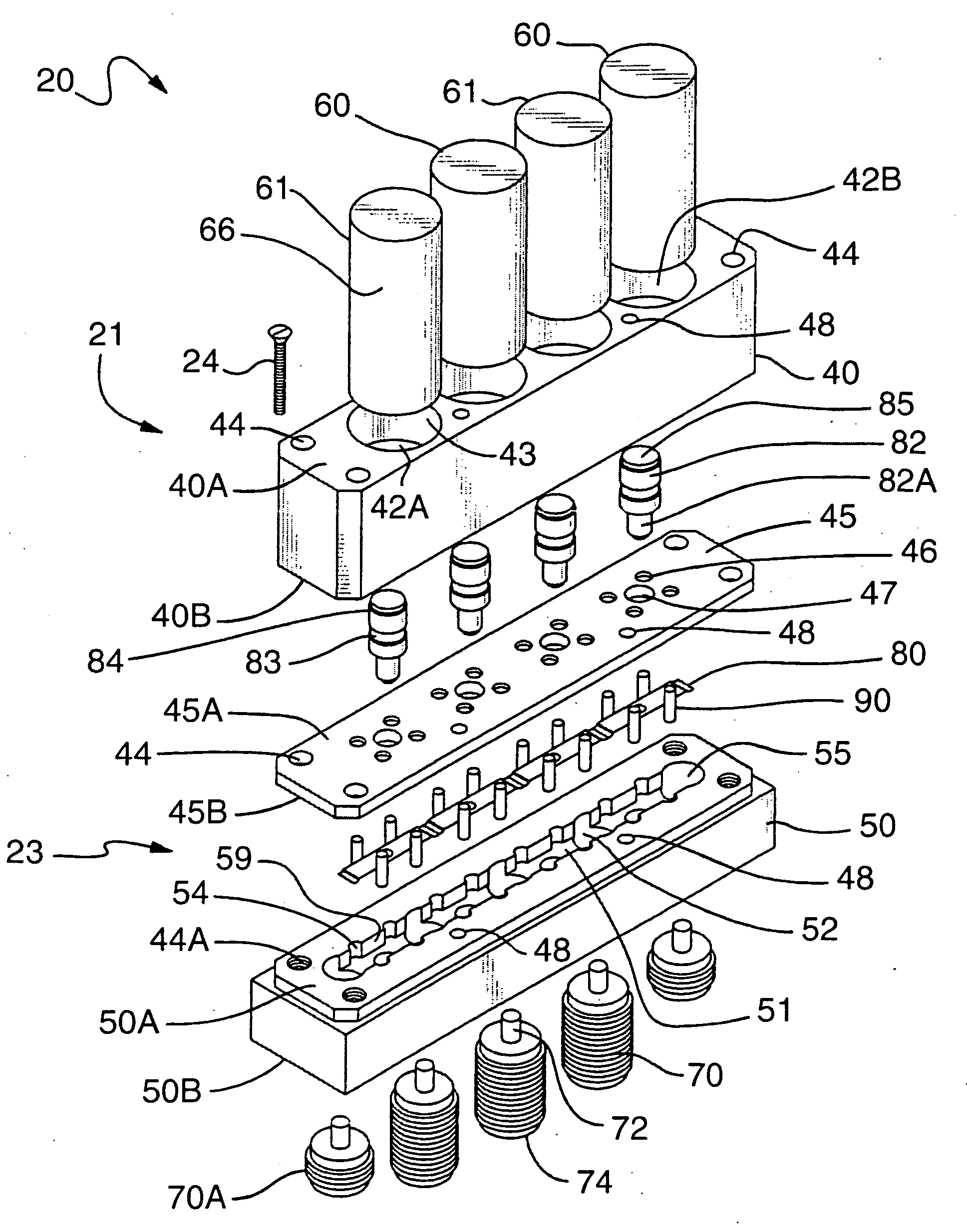
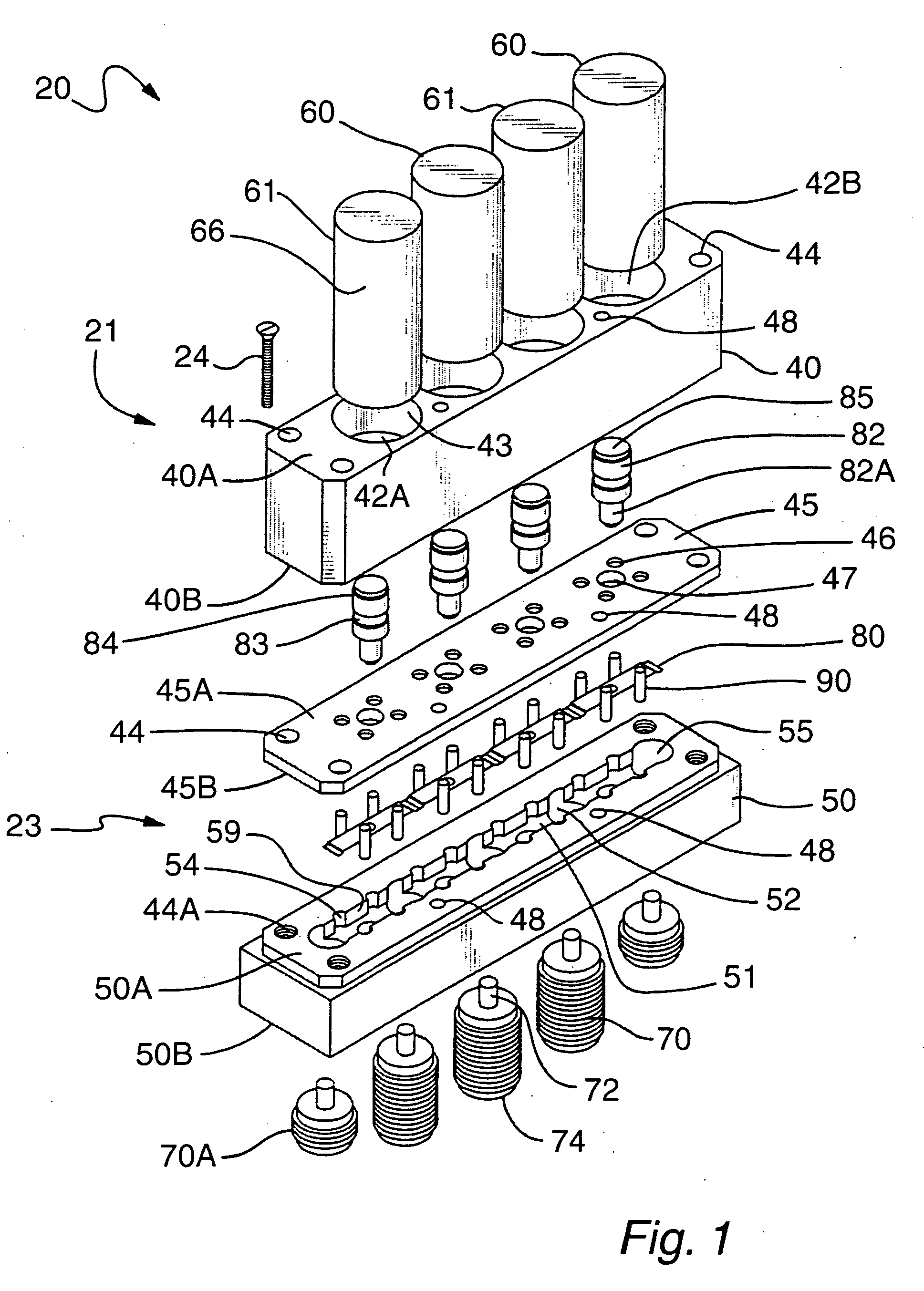
[0037]Referring to FIGS. 1-4a, a single pole double throw radio frequency absorptive switch assembly 20 is shown. Switch 20 has an actuator sub-assembly 21 and a housing 23. The housing 23 includes middle plate 45 and base 50. Middle plate 45 is located between case 40 and base 50. Screws or bolts 24 mounted in holes 44 and threaded holes 44A hold the switch assembly 20 together.

[0038]The actuator subassembly 21 includes a case 40 and actuators 60 and 61. Case 40 has a top surface 40A and a bottom surface 40B. Case 40 has four bores 42B with counterbores 42A that extend through case 40. Bores 42B define a bore wall 43. Screw holes 44 extend through case 40 for screws 24. Alignment dowel holes 48 are also located in case 40, middle plate 45 and base 50.

[0039]An actuator 60, preferably a solenoid or electromagnet, is mounted in two of counterbores 42A. An actuator 61, preferably a solenoid or electromagnet, is mounted in two other of counterbores 42A. Actuators 60 and 61 each have a f...


PUM


Abstract

An improved electromechanical RF switch provides enhanced reliability and lifespan by incorporating a middle plate between the case and base elements for locating the guide pins, reed holders and reeds to increase accuracy in critical component alignment. The middle plate reduces required precision during assembly of the switch, thus increasing assembly accuracy while reducing labor cost. The guide pins are made of a hard insulator such as glass to generate less wear particles, and the reed holder has a groove filled with lubricant to trap any wear particles that result from sliding friction during switch operation. Optionally, a low-friction bushing is used within the case bore to further reduce sliding friction during reed holder travel. The reeds are made of thin, flexible metal and have ends shaped so that when the ends contact switching terminals, a wiping action removes any surface contamination from both the reed ends and the terminals.

Description

CROSS-REFERENCES TO RELATED APPLICATIONS[0001]This application is a continuation-in-part of U.S. patent application entitled ELECTROMECHANICAL RADIO FREQUENCY SWITCH, Ser. No. 11 / 207,025 filed Aug. 19, 2005.BACKGROUND OF THE INVENTION[0002]1. Field of the Invention[0003]This invention relates to electromechanical relays for switching high-frequency signals with high reliability, long service life, stable insertion loss, stable return loss and high isolation.[0004]2. Description of the Prior Art[0005]Many different types of switches are known for the switching of radio frequency signals. Two main varieties of radio frequency switches are known as reflective switches and absorptive switches, wherein a reflective switch provides an open circuit termination at the output “off” port or terminal and an absorptive switch provides a 50-ohm termination at the output port or terminal. The ideal choice of switch type depends on the application. Radio frequency switches, as with other types of ...

Claims


Application Information

Patent Timeline
Patent Type & Authority Applications(United States)
IPC IPC(8): H01H53/00
CPCH01P1/125
Inventor RAKLYAR, ARONSIMKIN, GENNADYPOLISHCHUK, EFIMMEISAROSH, ALEXSANDER
Owner SCI COMPONENTS
Why Eureka
Try Eureka