Ink jet recording apparatus

a technology of recording apparatus and ink jet, which is applied in printing and other directions, can solve the problems of difficult effective expulsion of viscous ink around the clear portion, flight curvature, and failure to eject, and achieve the effect of efficiently expulsion of viscous ink around the nozzle orifi

Inactive Publication Date: 2005-06-21
SEIKO EPSON CORP
View PDF18 Cites 4 Cited by
  • Summary
  • Abstract
  • Description
  • Claims
  • Application Information

AI Technical Summary

Benefits of technology

[0007]The present invention has been achieved in the light of the aforementioned problems, and it is an object of the invention to provide an ink jet recording apparatus that is capable of expelling the viscous ink around the nozzle orifices efficiently.

Problems solved by technology

However, in the nozzle orifices located at the upper end or lower end to eject ink droplets less frequently, the ink is dried and become viscous near the nozzle orifices while printing, possibly causing the clogging.
From the time when the recording head is reciprocated once to make the printing to the time when the print data corresponding to one reciprocation is input, the recording head is enabled to stand by at the stand-by position, but the drying of the ink progresses while the stand-by, giving rise to an ejection failure such as flight curvature because the viscous ink resides near the nozzle orifices.
However, in the related ink jet recording apparatus, since the flushing operation is performed successively, a part of the viscous ink near the nozzle orifices is expelled by flushing to make a clear portion, and the ink is successively ejected through the clear portion, so that the viscous ink residing around the clear portion is difficult to expel effectively.

Method used


Image

  • Ink jet recording apparatus
  • Ink jet recording apparatus
  • Ink jet recording apparatus

Examples


Embodiment Construction

[0050]The preferred embodiments of the present invention will be described in detail with reference to the accompanying drawings.

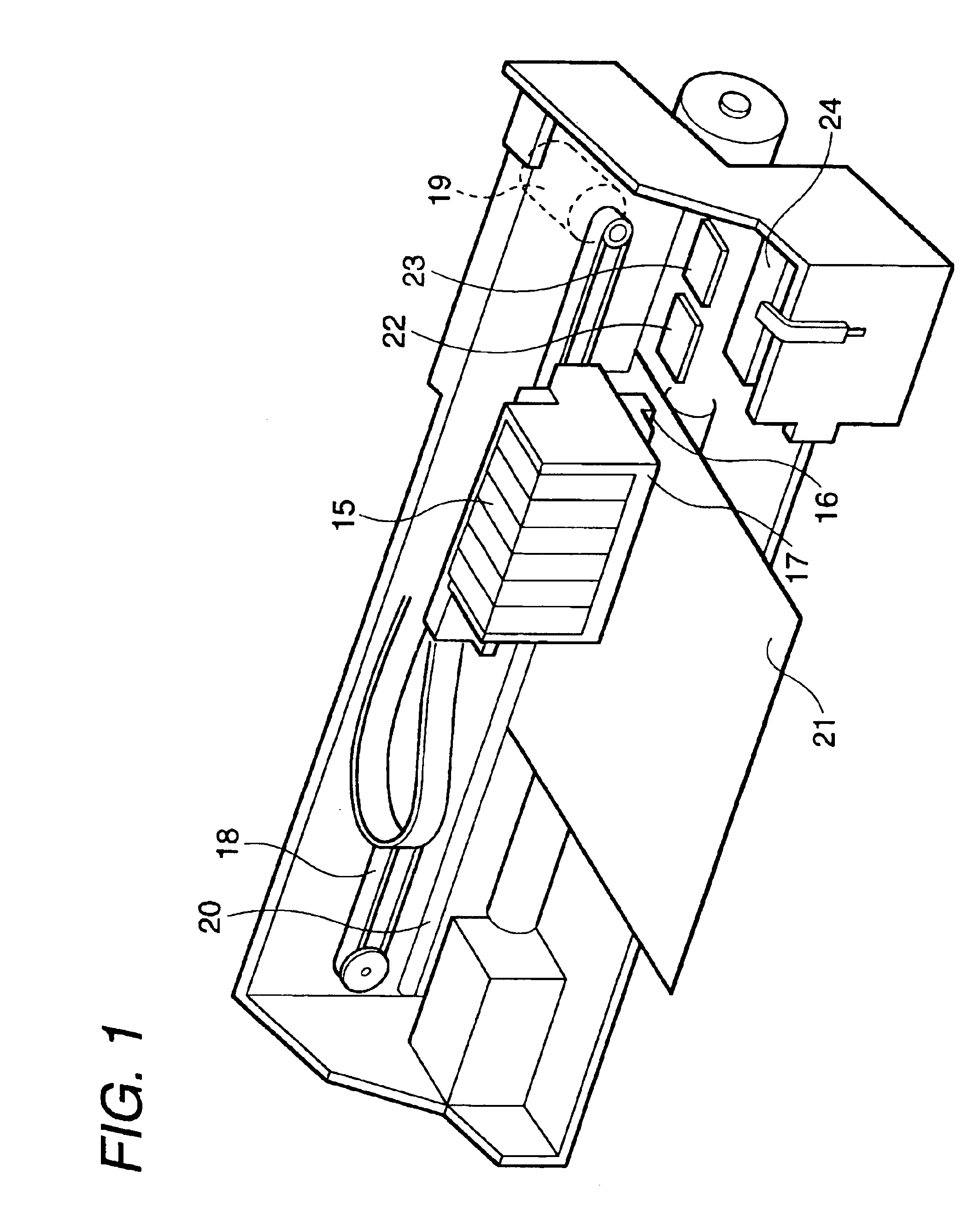
[0051]FIG. 1 illustrates an example of an ink jet recording apparatus. This apparatus comprises a carriage 17 with an ink cartridge 15 mounted thereon and a recording head 16 attached on a bottom face of the carriage 17.

[0052]The carriage 17 is connected to a stepping motor 19 via a timing belt 18, and reciprocated in a widthwise direction of the recording sheet 21 (main scanning direction), while being guided by a guide bar 20. Also, the carriage 17 has the recording head 16 on an opposite face (bottom face in this example) to the recording sheet 21. And the ink from the ink cartridge 15 is supplied into this recording head 16, which ejects ink droplets on the upper face of the recording sheet 21 while moving the carriage 17, thereby printing an image or character on the recording sheet 21 through use of a dot matrix.

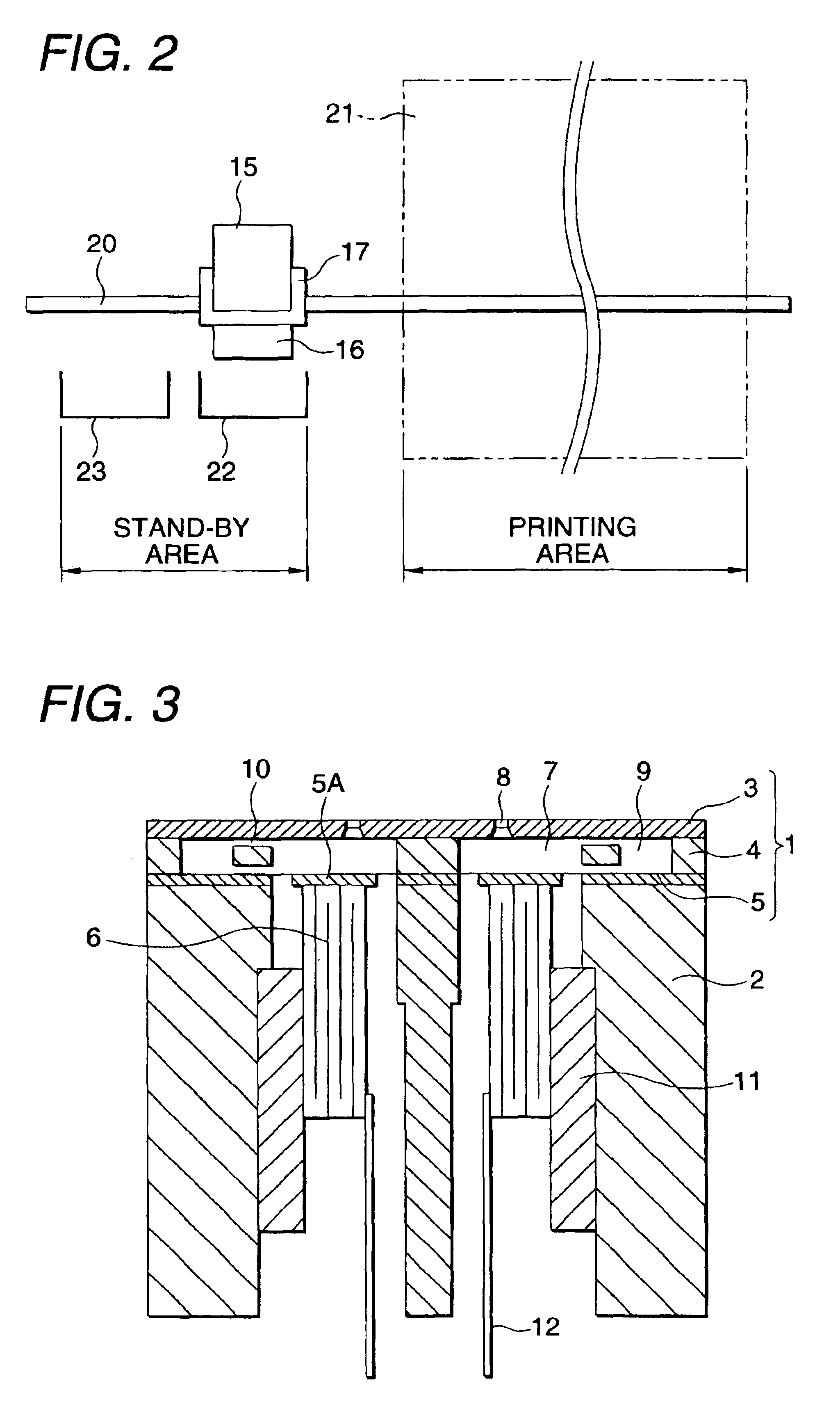
[0053]In a stand-by area within the mo...


PUM


Abstract

A pressure generator is driven to eject ink droplets from a nozzle orifice such that a plurality of flushing operations are intermittently repeated with a first time interval, when a recording operation of a recording head is not performed. Each flushing operation includes a plurality of ink ejections repeated for a predetermined times with a second time interval which is shorter than the first time interval. The ink near the nozzle orifice is residually vibrated between the flushing operations, so that the viscous ink is diffused and the viscous ink is effectively expelled.

Description

BACKGROUND OF THE INVENTION[0001]The present invention relates to an ink jet recording apparatus having an ink jet recording head for ejecting ink droplets in accordance with the print data and forming the dots on the recording medium.[0002]Generally, an ink jet recording head (hereinafter referred to as a “recording head”) comprises a plurality of nozzle orifices, a pressure generating chamber in communication with each nozzle orifice, and a piezoelectric vibrator for varying the pressure of the pressure generating chamber. And the recording head ejects the ink of the pressure generating chamber as ink droplets through nozzle orifices owing to a pressure change within the pressure generating chamber caused by vibrating the piezoelectric vibrator in accordance with a print signal.[0003]In the recording apparatus employing the above recording head, the recording head is mounted on a carriage capable of reciprocating in a main scanning direction, and ejects ink droplets onto the recor...

Claims


Application Information

Patent Timeline
Patent Type & Authority Patents(United States)
IPC IPC(8): B41J2/165B41J2/045B41J2/175B41J2/055
CPCB41J2/16526
Inventor SUZUKI, KAZUNAGA
Owner SEIKO EPSON CORP
Why Eureka
Try Eureka