Lash adjuster

a technology of lash adjustment and lash plate, which is applied in the direction of valve arrangement, mechanical equipment, machines/engines, etc., can solve the problems of valve opening and closing at wrong timing, valve being impulsively seated on the valve seat, and causing noise, so as to reduce the number of manufacturing steps, facilitate the flow, and effectively eliminate the effect of oil film

Inactive Publication Date: 2010-03-25
NTN CORP
View PDF4 Cites 4 Cited by
  • Summary
  • Abstract
  • Description
  • Claims
  • Application Information

AI Technical Summary

Benefits of technology

[0019]With the lash adjuster according to this invention, because the oil film expelling grooves are formed in the internal thread, using a tap having a thread that crosses the internal thread, each oil expelling groove has one end thereof open to the apex of the internal thread. Thus, engine oil in the oil film expelling grooves can more easily flow. This in turn makes it easier for engine oil present between the pressure flanks to flow into the oil film expelling grooves, and thus makes it possible to effectively eliminate oil film between the pressure flanks. Also, because the internal thread and the oil film expelling grooves can both be formed by a tap, it is possible to reduce the number of manufacturing steps and thus the manufacturing cost.
[0020]In the arrangement in which the helix direction of the internal thread 21 is opposite to the helix direction of the oil film expelling grooves 24 so that the thread of the tap crosses the internal thread, because the internal thread crosses the oil film expelling grooves at a large angle, it is possible to minimize the formation of burrs at portions where the respective oil film expelling grooves intersect the apex of the internal thread.
[0021]In the arrangement in which the tap has an outer diameter larger than the effective diameter of the internal thread, and a root diameter smaller than the effective diameter of the internal thread, it is possible to reliably form the oil film expelling grooves while keeping the apex of the internal thread intact.
[0022]In the arrangement in which the thread of the tap has a pitch smaller than the pitch of the internal thread, because the distance between the adjacent oil film expelling grooves is small, it is possible to effectively expel oil film between the pressure flanks.

Problems solved by technology

When such a valve operating mechanism is thermally expanded due to increased ambient temperature while the engine is running, due to differences in thermal expansion coefficient between component parts of the valve operating mechanism, gaps between the respective component parts of the valve operating mechanism (including the gap between the arm and the valve stem) may change, thus producing noise and causing the valve to be opened and closed at wrong timing.
Also, when the sliding portions of the valve operating mechanism become worn, gaps between the component parts of the valve operating mechanism (such as the gap between the valve and the valve seat) may change, thus producing noise.
If the screw rod is pushed into the housing, the pivot point of the arm moves, thus causing the valve to be impulsively seated on the valve seat and producing noise.
In the case of the former lash adjuster, because the oil film expelling grooves are formed parallel to the thread, the oil film expelling grooves are long, so that engine oil in the oil film expelling grooves is difficult to flow.
This in turn makes it difficult for engine oil present between the pressure flanks to flow into the oil film expelling grooves, and thus making it difficult to effectively prevent formation of oil film between the pressure flanks.
For the latter lash adjuster, because the internal thread is formed by a tap and the oil film expelling grooves are formed by broaching, a larger number of manufacturing steps are needed, and thus the manufacturing cost is high.
Also, if the internal thread is axially long, it is difficult to form oil film expelling grooves by broaching.

Method used


Image

  • Lash adjuster
  • Lash adjuster
  • Lash adjuster

Examples


Embodiment Construction

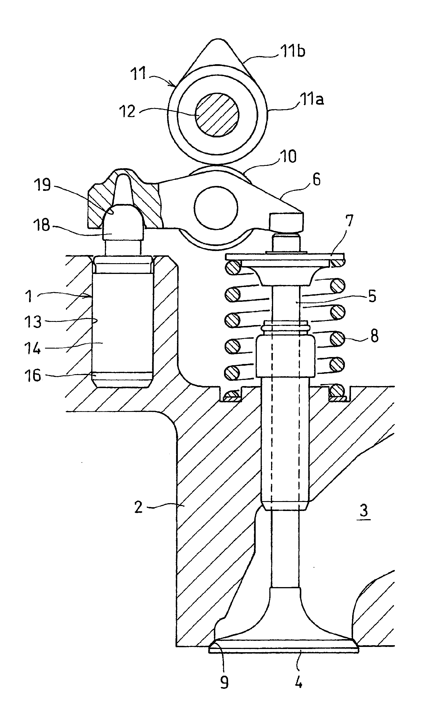
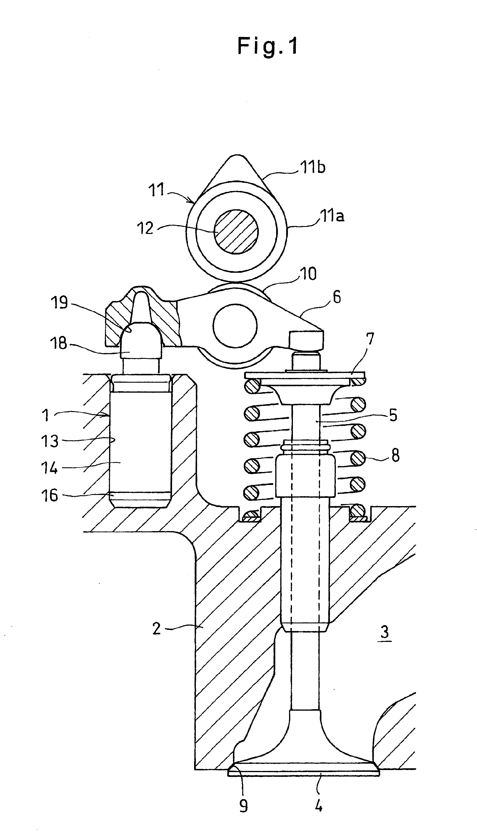
[0027]FIG. 1 shows a valve operating mechanism including a lash adjuster 1 embodying the present invention. This valve operating mechanism includes a valve 4 provided at an intake port 3 of an engine cylinder head 2, a valve stem 5 connected to the valve 4, and an arm 6 pivotally supported by the lash adjuster 1.

[0028]The valve stem 5 extends upwardly from the valve 4 and is slidably inserted through the cylinder head 2. An annular spring retainer 7 is fixed to the outer periphery of the valve stem 5 at its top end. A valve spring 8 is mounted between the bottom surface of the spring retainer 7 and the top surface of the cylinder head 2. The valve spring 8 biases the valve stem 5 upwardly through the spring retainer 7, thereby seating the valve 4 on a valve seat 9.

[0029]The arm 6 has one end thereof supported by the lash adjuster 1, and the other end in contact with the top end of the valve stem 5. A roller 10 is mounted to the central portion of the arm 6. The roller 10 is in conta...


PUM


Abstract

A lash adjuster is provided which includes a cylindrical housing having an open top and formed with an internal thread on an inner periphery thereof, a screw rod having an external thread formed on an outer periphery thereof and in threaded engagement with the internal thread, and a spring biasing the screw rod outwardly of the housing. Each of the internal thread and the external thread having a pressure flank configured to receive pressure when a force that tends to push the screw rod into the housing acts on the screw rod, and a clearance flank having a smaller flank angle than the pressure flan. The screw rod has an end protruding from the housing and configured to support an arm of a valve operating mechanism so as to be pivotable about this end. Oil film expelling grooves are formed in the pressure flank of the external thread, using a tap having a thread that extends so as to cross the internal thread.

Description

BACKGROUND OF THE INVENTION[0001]This invention relates to a lash adjuster mounted in an engine valve operating mechanism.[0002]Many known valve operating mechanisms include an arm that pivots corresponding to the rotation of a cam, thereby pushing a valve stem connected to a valve provided at an intake or exhaust port of an engine and moving the valve.[0003]When such a valve operating mechanism is thermally expanded due to increased ambient temperature while the engine is running, due to differences in thermal expansion coefficient between component parts of the valve operating mechanism, gaps between the respective component parts of the valve operating mechanism (including the gap between the arm and the valve stem) may change, thus producing noise and causing the valve to be opened and closed at wrong timing. Also, when the sliding portions of the valve operating mechanism become worn, gaps between the component parts of the valve operating mechanism (such as the gap between the...

Claims


Application Information

Patent Timeline
Patent Type & Authority Applications(United States)
IPC IPC(8): F01L1/18
CPCF01L1/185F01L1/22F01L2820/032F01L2105/00F01L2810/02F01L1/2405F01L2305/00
Inventor YAMAGUCHI, KATSUHISABUNKO, HIROSHIMAENO, EIJI
Owner NTN CORP
Why Eureka
Try Eureka