Suction bell for breast pump

a technology of suction bell and breast pump, which is applied in the field of breast milk collection, can solve the problems of complex structure, inconvenient cleaning and sterilization of the device between uses, and the gascoigne device is not and is not suitable for practical use, and achieves the effect of simple and effective structure, easy assembly and disassembly

Inactive Publication Date: 2002-10-08
AMEDA
View PDF16 Cites 183 Cited by
  • Summary
  • Abstract
  • Description
  • Claims
  • Application Information

AI Technical Summary

Benefits of technology

Accordingly, it is an object of the present invention to provide an improved suction bell for a breast pump that avoids the aforementioned drawbacks of prior art suction bells by means of a simple and effective structure for simulating a normal suckling action when operated, and which can be easily assembled and disassembled for cleaning and sterilization by means readily available in the home, that is, by immersion in boiling water.

Problems solved by technology

However, the Gascoigne device was not and is not suitable for practical use for a variety of reasons.
First, its complicated structure would be costly with regard to production and maintenance.
Second, and even more essential for user acceptance, is the virtual impossibility of cleaning and sterilizing the device between uses by normal means available in a household.
Other disadvantages result from the need to apply both pressure and suction pulses, requiring three pneumatic lines, one for continuous suction applied inside the liner and acting directly upon the breast, and two pulse lines, one for suction pulses and one for pressure pulses applied outside the liner at different portions thereof.
While the structure of the breast pump embodiment is relatively simple, compared with Gascoigne, cleaning and safe sterilization are not easily possible.

Method used


Image

  • Suction bell for breast pump
  • Suction bell for breast pump
  • Suction bell for breast pump

Examples


Embodiment Construction

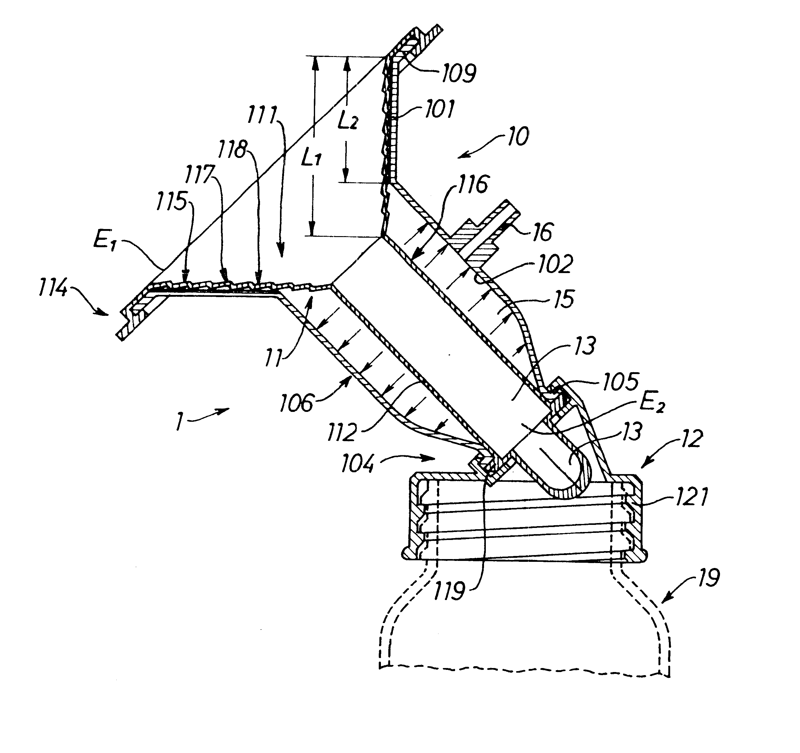
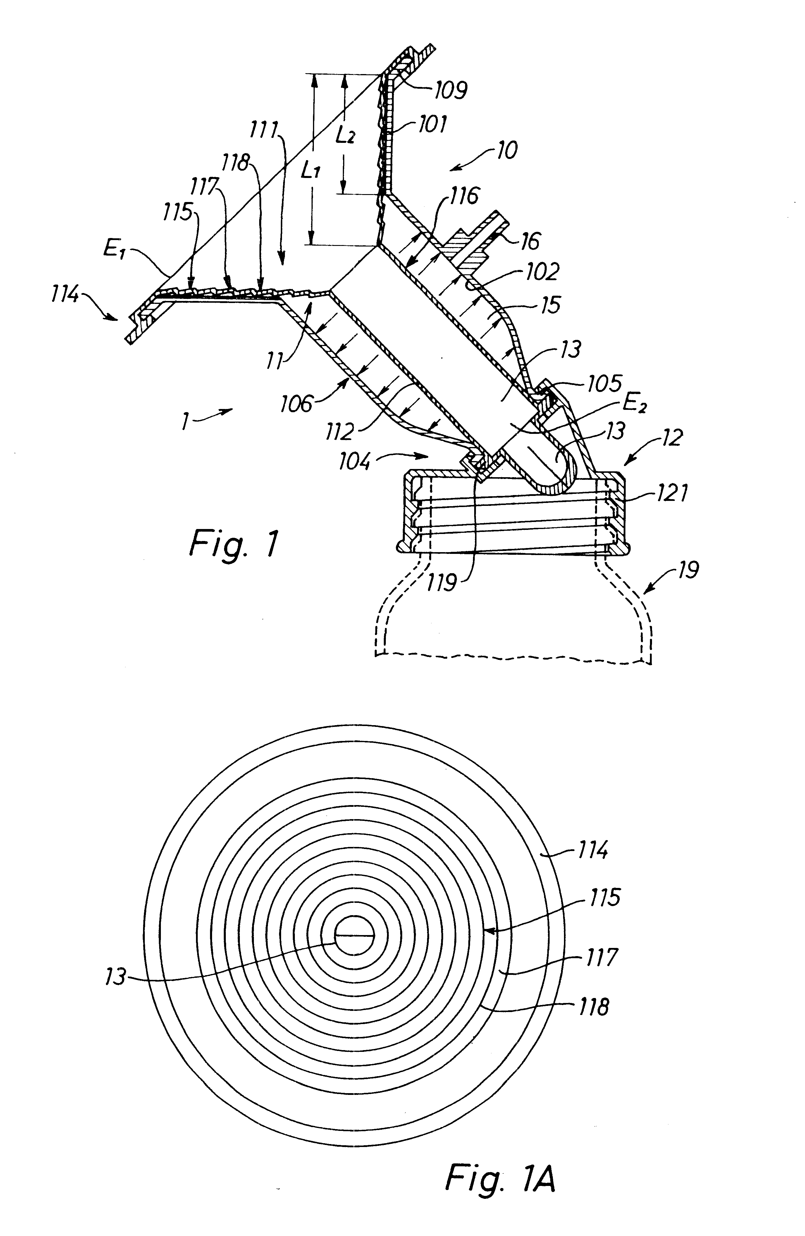
The suction bell 1 shown schematically in FIG. 1 in longitudinal section consists essentially of a rigid outer shell 10, liner 11, and connector 12. The suction bell is funnel-shaped and has a substantially Y-shaped cross section as depicted in FIG. 1. The shell has a conical top portion 101 with an open upper end E.sub.1 and a cylindrical body portion 106 with an open lower end E.sub.2. At its open upper end E.sub.1, top portion 101 of the shell is provided with a rim 109 for a sealable yet easily mountable and removable snap-connection with the peripheral lip 114 of the liner which wraps about the rim. The angular position of rim 109 relative to conical top portion 101, with the rim extending along a plane normal to the longitudinal axis of the shell, is preferred for practical reasons but is not believed to be critical for achieving a sealing connection between the parts. An annular shoulder 105 extends about the shell's lower end E.sub.2 and serves to effect a sealing connection...


PUM


Abstract

A suction bell assembly, and an elastomeric liner therefor, are disclosed in which the bell includes a rigid outer shell (10,310) of generally Y-shaped axial cross section with a conical top portion (101) and a cylindrical body portion (106). A thin, flexible, elastic liner (11) is disposed within the shell and has a conical and preferably corrugated upper portion (111) disposed within the conical top portion of the shell and a peripheral lip (114) for sealingly engaging a rim (19) extending about the shell's top portion. The liner also includes an elongated tubular portion 112 spaced normally inwardly from the shell's inner surface, the tubular portion including a resilient annular flange (119) that sealingly engages a shoulder at the lower end of the shell to maintain the liner in an axially stretched and tensioned state. one-way valve means (13,43) is formed integrally with the liner and is disposed at the lower end of the tubular portion below the flange (119). The valve means (13,43) includes a calotte-shaped closure portion (131) having at least one slit (28,438,439) to permit the passage of milk downwardly through the lower end of the liner. In preferred embodiments, each slit (28,438,439) has offset but communicating inner and outer portions (28a,28b,438a,438b, 439a,439b). Means are also disclosed for allowing swivel action of the shell (310) in relation to a connector (32) for detachably connecting the suction bell to a milk-collecting bottle.

Description

FIELD OF THE INVENTIONThe present invention generally relates to the collection of breast milk and specifically to an improved suction bell for a breast pump and to an insert or liner for such a suction bell.PRIOR ARTBreast pumps of various designs have been known since early in the twentieth century and a large number of patents relating to that subject matter have issued since. Common features of such devices are a generally flared member (commonly termed a "suction bell") adapted to encompass the nipple region of a mother's breast, a source of cyclic sub-atmospheric pressure (also termed a suction device or pump), and milk collecting means usually in the form of a bottle.Obviously, an essential factor, both with regard to a user's comfort as well as to stimulation of the lactation process are the feel of the suction bell when in contact with a breast and the impact of the cyclic pressure changes. In line with these requirements, U.S. Pat. No. 2,542,505 (to G. H. Gascoigne) disclo...

Claims


Application Information

Patent Timeline
Patent Type & Authority Patents(United States)
IPC IPC(8): A61M1/06A61M1/00
CPCA61M1/06A61M1/0068A61M1/064A61M1/066A61M1/81A61M1/0697A61M1/06935
Inventor SCHLENSOG, KLAUS
Owner AMEDA
Why Eureka
Try Eureka