
Device for supporting chromophore elements

a technology of chromophore elements and devices, applied in the direction of optical elements, fluorescence/phosphorescence, instruments, etc., can solve the problems of considerable difficulties in coupling excitation light into the guiding layer of the substrate, and achieve the effect of improving the signal-to-noise ratio

Active Publication Date: 2005-09-15
GENEWAVE SAS
View PDF7 Cites 123 Cited by
  • Summary
  • Abstract
  • Description
  • Claims
  • Application Information

AI Technical Summary

Benefits of technology

[0006] An object of the invention is to provide a solution to this problem that is simple and effective.
[0008] In the device of the invention, the light for exciting the chromophore elements is generated in the planar waveguide itself, thus avoiding any problems with coupling said light into the waveguide. In addition, the excitation light is itself produced by direct (non-guided) illumination of the portion of the waveguide in which the photoluminescent constituents are to be excited, which can be done in ordinary manner with quite broad tolerance, typically greater than 10 μm.
[0014] According to another characteristic of the invention, wavelength filter means are provided in the planar waveguide to eliminate from the light emitted by the photoluminescent constituents those wavelengths that are identical or close to the wavelengths of the fluorescence emitted by the chromophore elements.
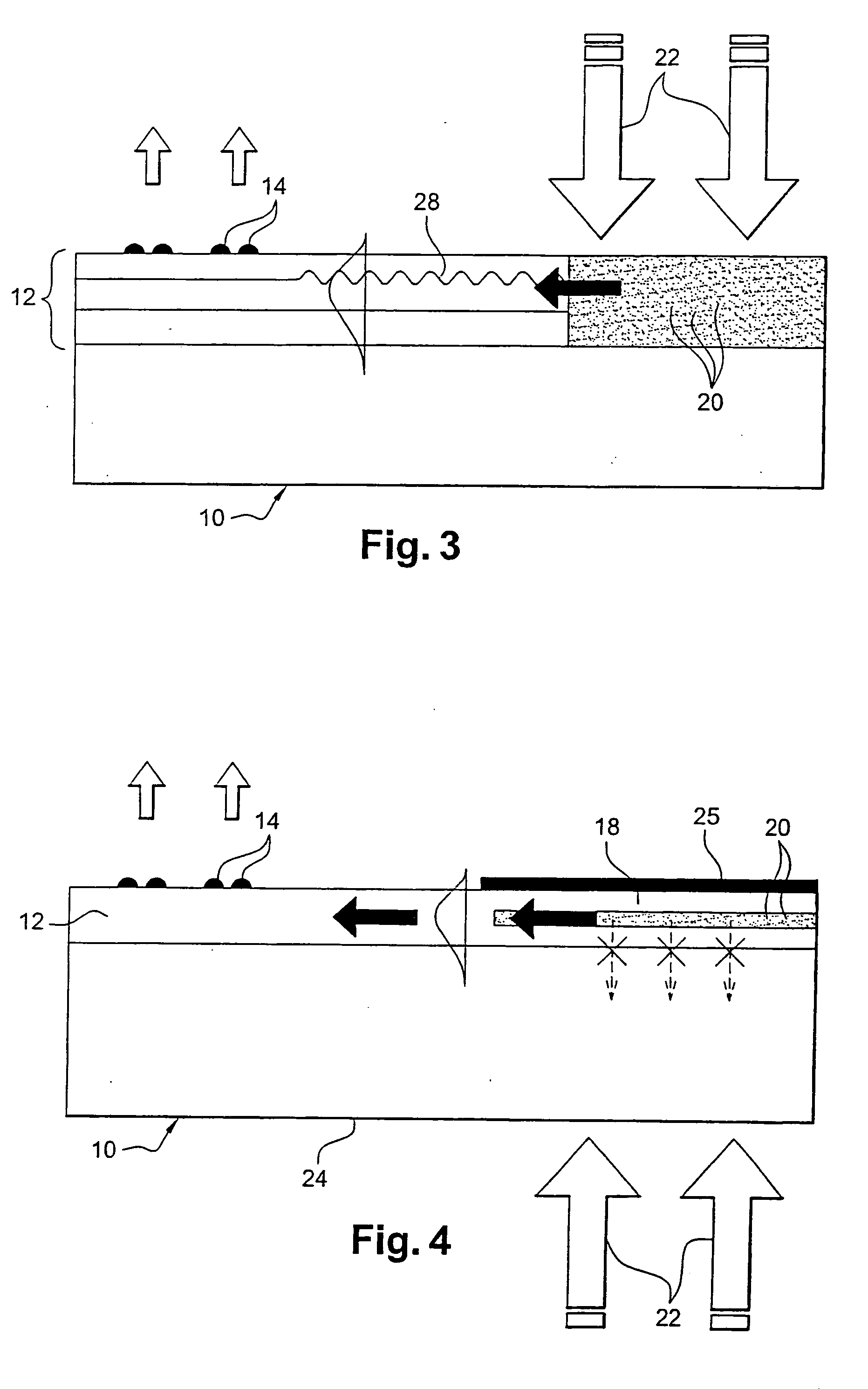
[0033] To prevent the primary excitation light and the non-guided luminescence that might be diffused via the substrate managing to constitute a harmful background signal, an absorbent layer may be disposed over part or all of the substrate, being situated beneath the planar waveguide and consuming photons emitted from said waveguide.
[0039] In the liquid medium, only those chromophore elements that are held stationary on the surface of the device are excited by the evanescent portion of the guided wave, and not those chromophore elements that are in suspension, thereby considerably improving the signal-to-noise ratio and making it possible to measure the hybridization signal with time resolution.

Problems solved by technology

The practical difficulties associated with coupling excitation light into the guiding layer of the substrate are therefore considerable.

Method used


Image

  • Device for supporting chromophore elements
  • Device for supporting chromophore elements
  • Device for supporting chromophore elements

Examples


Embodiment Construction

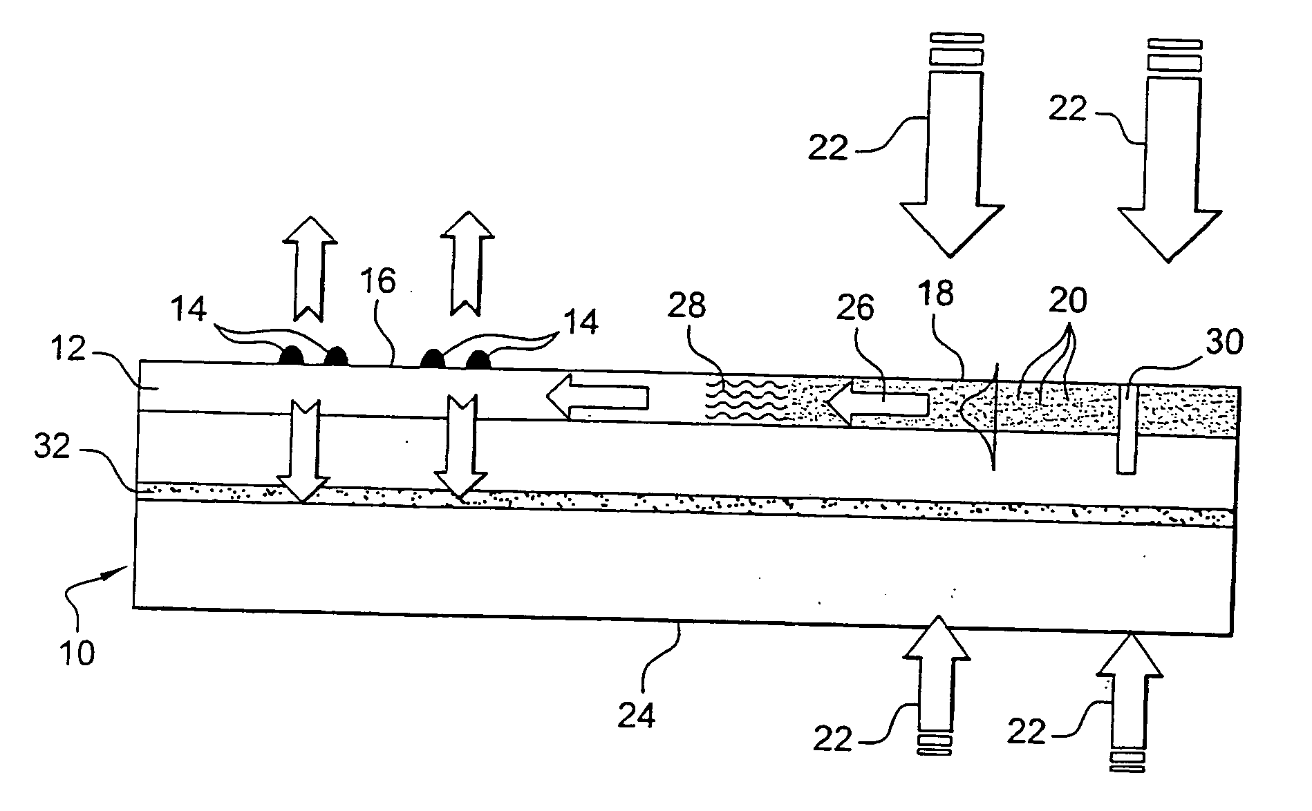
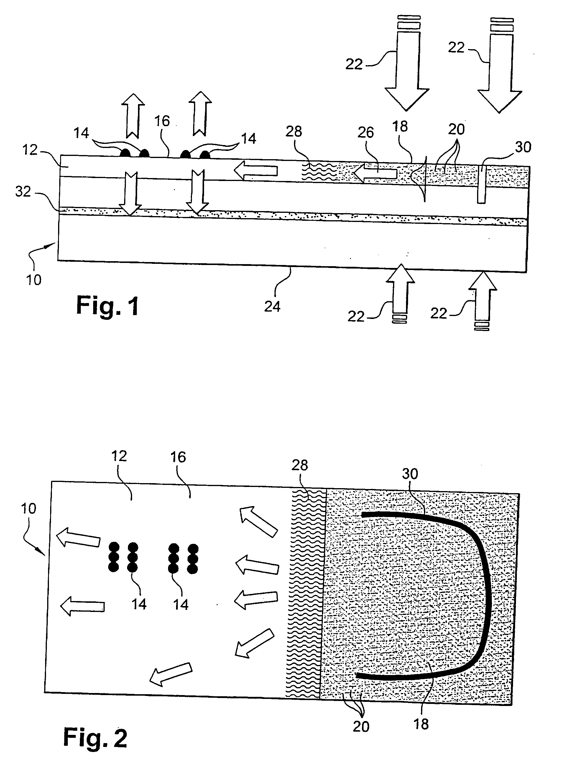
[0047] The device shown in FIGS. 1 and 2 comprises a substrate 10 of conventional type having a top layer 12 for carrying chromophore elements 14 on a portion 16 of its surface, which layer is made of a material having a high refractive index, e.g. greater than about 1.6, and forms a planar waveguide.

[0048] A portion 18 of this layer 12, adjacent to the portion 16 for carrying the chromophore elements 14, contains photoluminescent constituents 20 which emit luminescence in guided mode in the layer 12 on being excited by primary excitation light 22 directly illuminating either the portion 18 of the layer 12 containing the photoluminescent constituents 20, or the opposite face 24 of the substrate 10, as shown diagrammatically in FIG. 1.

[0049] The photoluminescent components 20 are selected, on being excited by the light 22, to emit luminescence at the excitation wavelengths for the chromophore elements 14. The chromophore elements are then excited by the evanescent portion of the gu...


PUM


Abstract

A device for supporting chromophore elements suitable for emitting fluorescence in response to light excitation, the device comprising a substrate having a surface layer carrying the chromophore elements, forming a planar waveguide, and containing photoluminescent constituents which emit guided luminescence at the excitation wavelength(s) of the chromophore elements when they are excited by primary excitation light illuminating the surface layer. The invention is particularly applicable to biochip type devices.

Description

[0001] The invention relates to a device for supporting chromophore elements, in particular devices such as those commonly called “biochips”. BACKGROUND OF THE INVENTION [0002] In such devices, a generally multi-layer substrate carries chromophore elements that are chemical molecules or biological molecules, dye elements added or grafted to the chemical biological molecules, or semiconductor nanostructures such as quantum boxes or wires that respond to excitation by appropriate light by emitting fluorescence at a wavelength that depends on their nature. This fluorescence makes it possible in particular to identify and find on the substrate molecules that have responded to given treatments. [0003] Proposals have already been made in patent applications WO-A-02 / 16912, FR 01 / 15140, and FR 02 / 10285 in the names of the same inventors, for means enabling the excitation intensity of chromophore elements to be reinforced, and thus to reinforce the fluorescence emitted by said elements. In p...

Claims


Application Information

Patent Timeline
IPC IPC(8): G01N21/55G01N21/64G01N21/77G02B6/42
CPCG01N21/648G01N21/6458G01N21/7703G01N2021/6419G01N2021/6421G01N2021/6441G01N2021/6471G02B6/42
Inventor WEISBUCH, CLAUDE
Owner GENEWAVE SAS
Learn More