
System and method for inductively charging a battery

a battery and inductive charging technology, applied in the field of system and method for inductive charging of batteries, can solve the problems of not all batteries are easily charged inductively, li-ion batteries are unable to absorb an overcharge, and li-ion batteries are not as straightforward as other batteries, so as to achieve the effect of increasing current through the primary coil

Active Publication Date: 2011-08-23
PHILIPS IP VENTURES BV
View PDF31 Cites 119 Cited by
  • Summary
  • Abstract
  • Description
  • Claims
  • Application Information

AI Technical Summary

Benefits of technology

The system effectively prevents overcharge and ensures full charging of lithium-ion batteries while maintaining a lightweight and cost-effective design, suitable for portable devices by using a feedback mechanism to adjust power delivery and protect the battery from harmful conditions.

Problems solved by technology

However, not all batteries are easily charged inductively.
Recharging Li-Ion batteries is not as straightforward as that of other batteries.
Li-Ion batteries are unable to absorb an overcharge.
If a constant current is applied to a fully charged Li-Ion battery, metallic lithium plating may develop which could lead to failure of the battery.
Conversely, charging a Li-Ion battery to full capacity presents some difficulty.
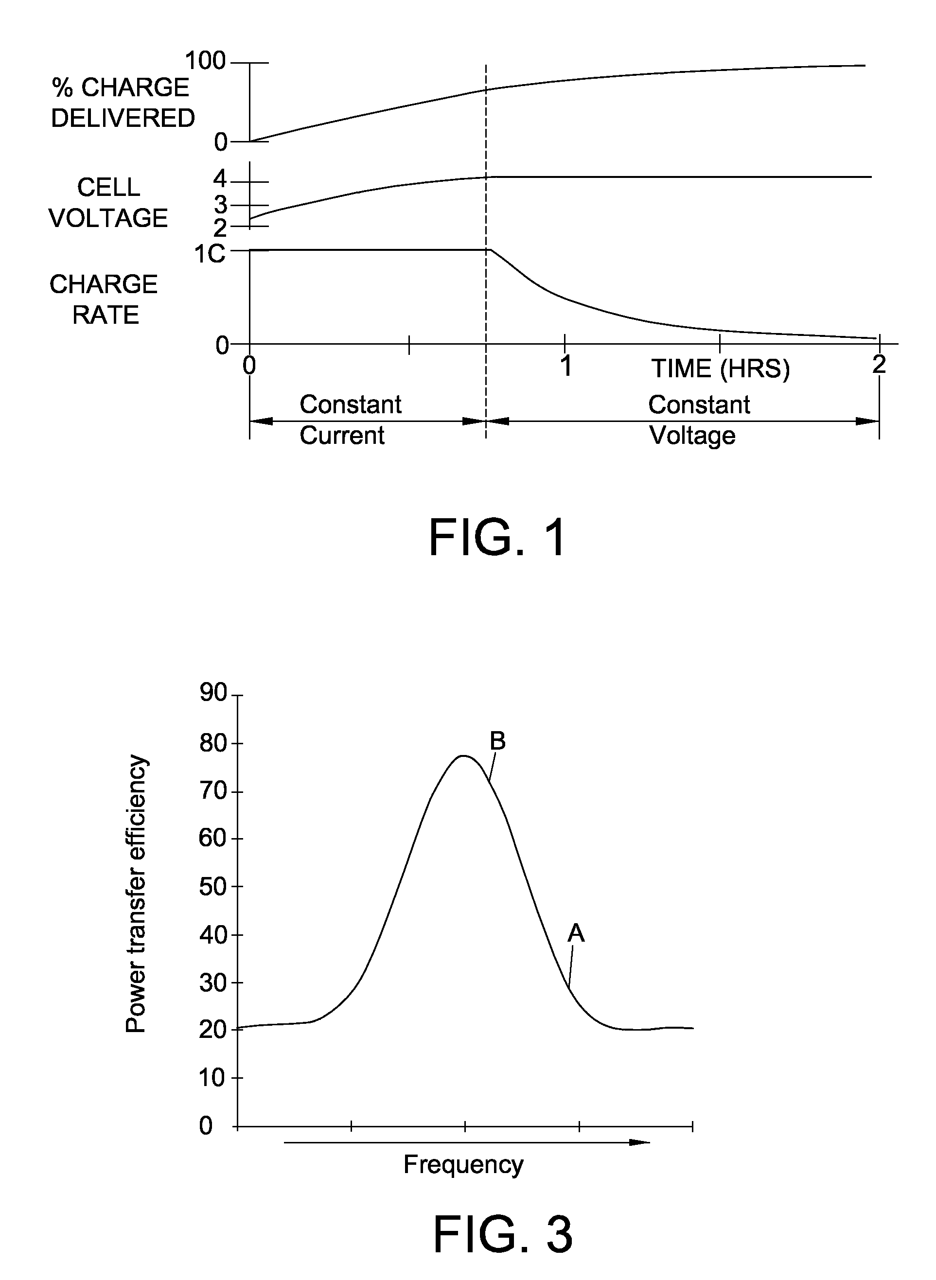
However, when the Li-Ion battery reaches a maximum voltage, the Li-Ion battery may not be fully charged.
If a constant current is continually applied to the battery after the battery has reached its maximum voltage, then the battery could be overcharged, which could lead to premature battery failure.
If the charging of a Li-Ion battery does not follow the charging profile shown in FIG. 1, then there is a risk that the battery will not be fully charged or that the charging will damage the battery.
The charging of a Li-Ion battery is further complicated because the battery is often not fully discharged before charging.
Charging Li-Ion batteries is especially problematic where inductive charging is used.
Because there is no physical connection between the battery and the battery charger, information regarding the state of the battery is not readily available to the battery charger.
Thus, complex circuitry to monitor the charge state of the battery and relay that information to the inductive charger increases the cost, size and weight of the portable device.

Method used


Image

  • System and method for inductively charging a battery
  • System and method for inductively charging a battery
  • System and method for inductively charging a battery

Examples


Embodiment Construction

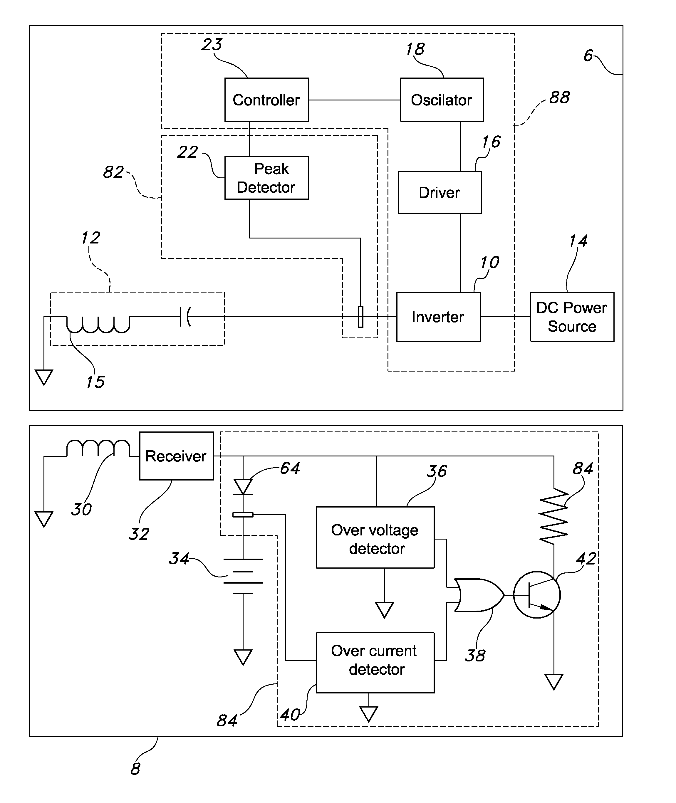
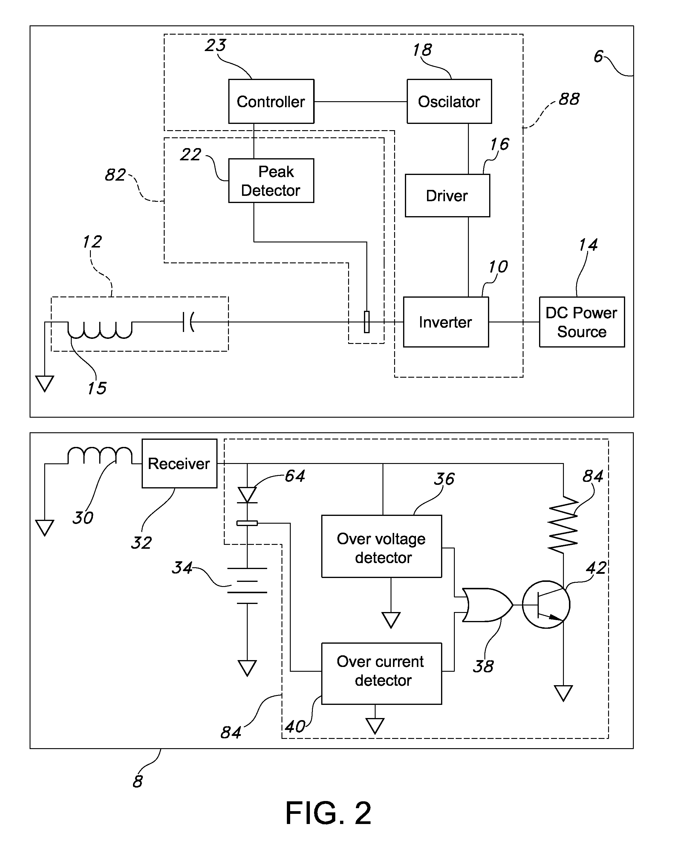
[0033]An inductive charging system in accordance with an embodiment of the present invention in shown in FIG. 2. The inductive charging system 4 is configured to inductively charge a battery having a nonlinear charging profile, such as a Li-Ion battery. The system 4 generally includes a charger circuit 6 and secondary circuit 8. The charger circuit 6 generally includes a primary coil 15, a frequency controller 80 for applying power to the primary coil at a desired frequency and a feedback detector 82 for receiving feedback from the secondary circuit 8. The secondary circuit 8 generally includes a secondary coil 30 for receiving inductive power from the charger circuit 6 and a feedback mechanism 84 for providing feedback to the charger circuit 6 indicative of the voltage or current in the secondary circuit 8. The frequency controller 80 varies the frequency of the power applied to the primary coil 15 as a function of the feedback from the secondary circuit 8. Although described in co...


PUM


Abstract

An inductive charging system for recharging a battery. The system includes a charger circuit and a secondary circuit. The secondary circuit includes a feedback mechanism to provide feedback to the charger circuit through the inductive coupling of the primary coil and the secondary coil. The charger circuit includes a frequency control mechanism for controlling the frequency of the power applied to the primary coil at least partly in response to the feedback from the feedback mechanism.

Description

BACKGROUND OF THE INVENTION[0001]Charging of batteries with an inductive power supply is well-known. Inductive charging of batteries for electric automobiles as well as the charging of small electric appliance batteries such as those for toothbrushes has met some amount of success. Because inductive charging does not require a physical connection between the battery and the charger, the charging is considerably more convenient. However, not all batteries are easily charged inductively. Lithium-ion batteries (Li-Ion) are one such type of battery.[0002]Recharging Li-Ion batteries is not as straightforward as that of other batteries. Li-Ion batteries are unable to absorb an overcharge. If a constant current is applied to a fully charged Li-Ion battery, metallic lithium plating may develop which could lead to failure of the battery. Thus, care should be taken not to overcharge the battery.[0003]Conversely, charging a Li-Ion battery to full capacity presents some difficulty. The maximum ...

Claims


Application Information

Patent Timeline
Patent Type & Authority Patents(United States)
IPC IPC(8): H02J7/00
CPCH02J7/0072H02J7/025H02J50/12H02J50/80H02J7/00034H02J50/90H02J7/0048H04B5/24H04B5/79
Inventor BAARMAN, DAVID W.LORD, JOHN J.STIEN, NATHAN P.
Owner PHILIPS IP VENTURES BV
Learn More