Carrier and attachment method for load-bearing fabric

a carrier and fabric technology, applied in the field of carrier and fabric, can solve the problems of fabric unraveling or separating along the periphery of the fabric, the use of expensive looms and stretching machinery, and the inability of conventional attachment methods to provide the necessary strength and durability to withstand the forces applied to the fabric, etc., to achieve the effect of simple and effective, strong and durable interconnection, and relatively simple and inexpensive manufacturing of carrier and fabri

Inactive Publication Date: 2005-05-31
ILLINOIS TOOL WORKS INC
View PDF63 Cites 118 Cited by
  • Summary
  • Abstract
  • Description
  • Claims
  • Application Information

AI Technical Summary

Benefits of technology

[0015]In one embodiment, the tool also includes one or more alignment rollers that initially align the carrier and frame before these components pass between the drive and primary rollers. The tool also may include a stop to prevent the rollers from crushing the carrier and / or frame when joining these components.
[0016]The present invention provides a simple and effective method for attaching a load-bearing fabric to a support structure. The encapsulated bond of the preferred embodiment provides a strong and durable interconnection between the carrier and the fabric. Also, because the carrier is not bonded to the fabric while in the stretched condition, manufacture of the carrier and fabric is relatively simple and inexpensive. Further, the expansion joints provide controlled and consistent stretch along the carrier. Additionally, the corner joints permit the fabric to be stretched without stretch of the carrier or with stretch of the carrier limited to the corner regions. Moreover, the interlocking indexing features on the carrier and frame ensure the fabric is stretched the desired amount when the carrier and frame are joined. Accordingly, the present invention provides for an inexpensive yet strong and highly durable attachment. In addition, the waterfall-type flexible component provides a leg-stress relieving feature that is easily incorporated into the chair without significantly compromising the tension of the load-bearing fabric, and thus firmness of the seat. Furthermore, the tool of the present invention makes it possible to join the carrier to the frame in an efficient manner that significantly reduces production time.

Problems solved by technology

One particularly important challenge related to the use of load-bearing fabric is attaching the fabric to the support structure.
Conventional attachment methods often fail to provide the necessary strength and durability to withstand the forces applied to the fabric.
In some applications, the bond itself may fail and in other applications, the method of attachment may cause the fabric to unravel or separate along the periphery of the fabric.
In such applications, the challenge is to secure the carrier in a way that provides a strong and durable bond without damaging or promoting unraveling of the fabric.
This operation involves the use of expensive looms and stretching machinery.
Further, when the molded carrier and fabric emerge from the mold, the force of the stretched fabric can cause the carrier to deform, for example, to bow or “potato chip.” This creates the need to return the carrier to the desired shape, typically using additional machinery, prior to attachment to the support structure.
As can be seen, encapsulation requires a relatively complex manufacturing process that employs expensive looms and stretching machinery.

Method used


Image

  • Carrier and attachment method for load-bearing fabric
  • Carrier and attachment method for load-bearing fabric
  • Carrier and attachment method for load-bearing fabric

Examples


Embodiment Construction

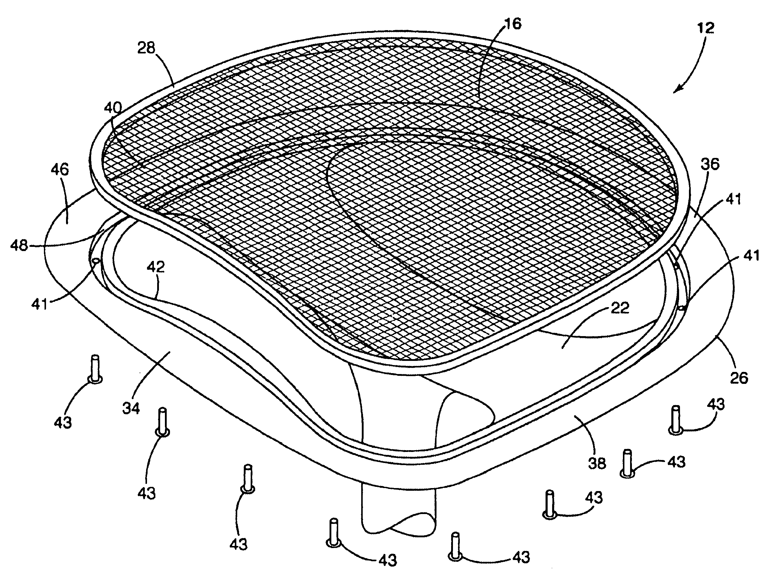
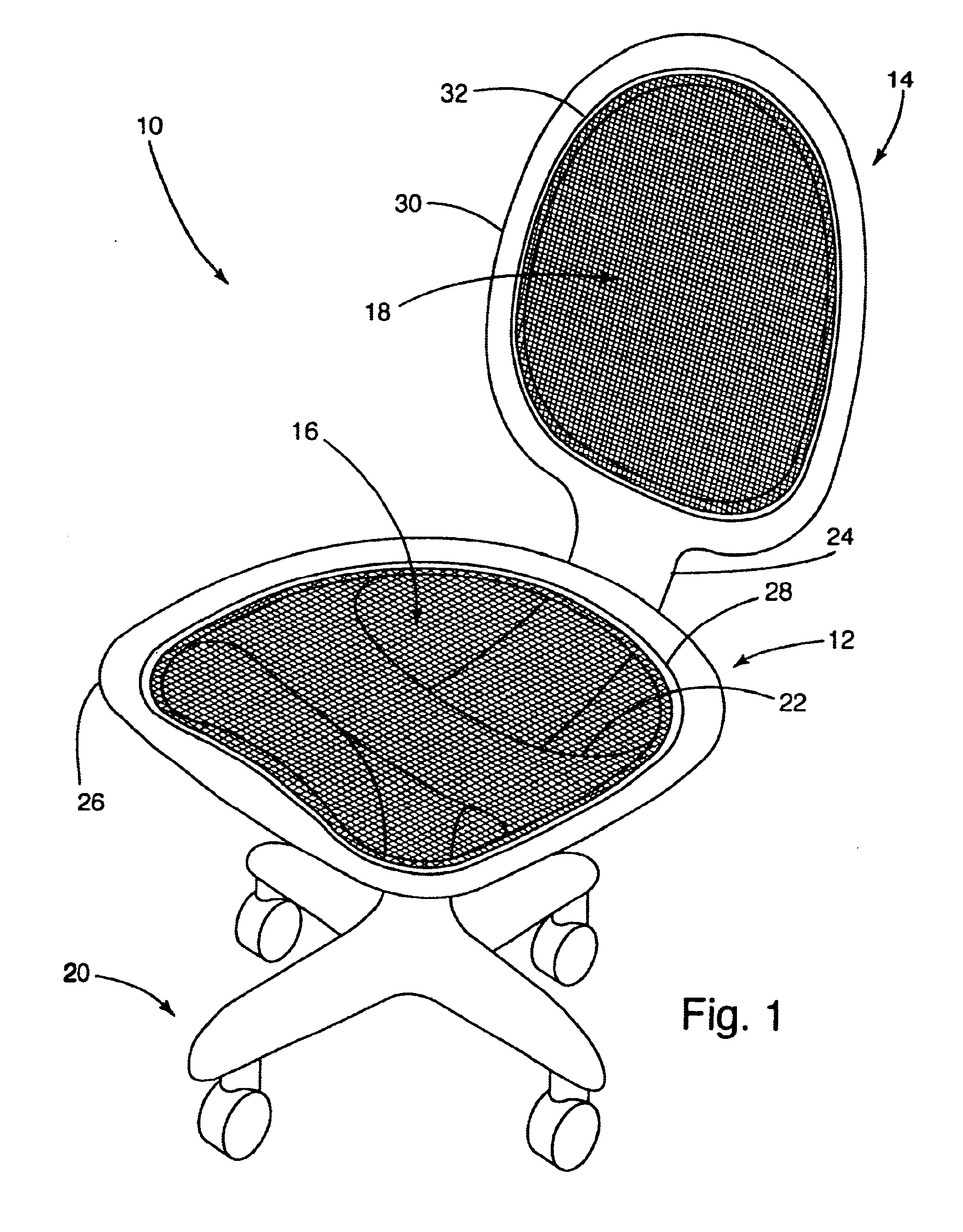
[0053]For purposes of disclosure, and not limitation, the present invention is described in connection with an office chair 10 having load-bearing fabric that forms the seat and back of the chair. The present invention is well-suited for use in a wide variety of other applications incorporating load-bearing fabric, such as other furniture applications, keyboard trays, mouse trays and cots. In the following description, the terms “inner,”“outer,”“inwardly,”“outwardly,”“upper” and “lower” are used to refer to directions relative to the geometric center of the fabric. Additionally, the word “expand” means to stretch, deform or otherwise increase the size of the object; the word “stretch” means to expand primarily through longitudinal elongation; and the word “deform” means to expand primarily through deflection or bending.

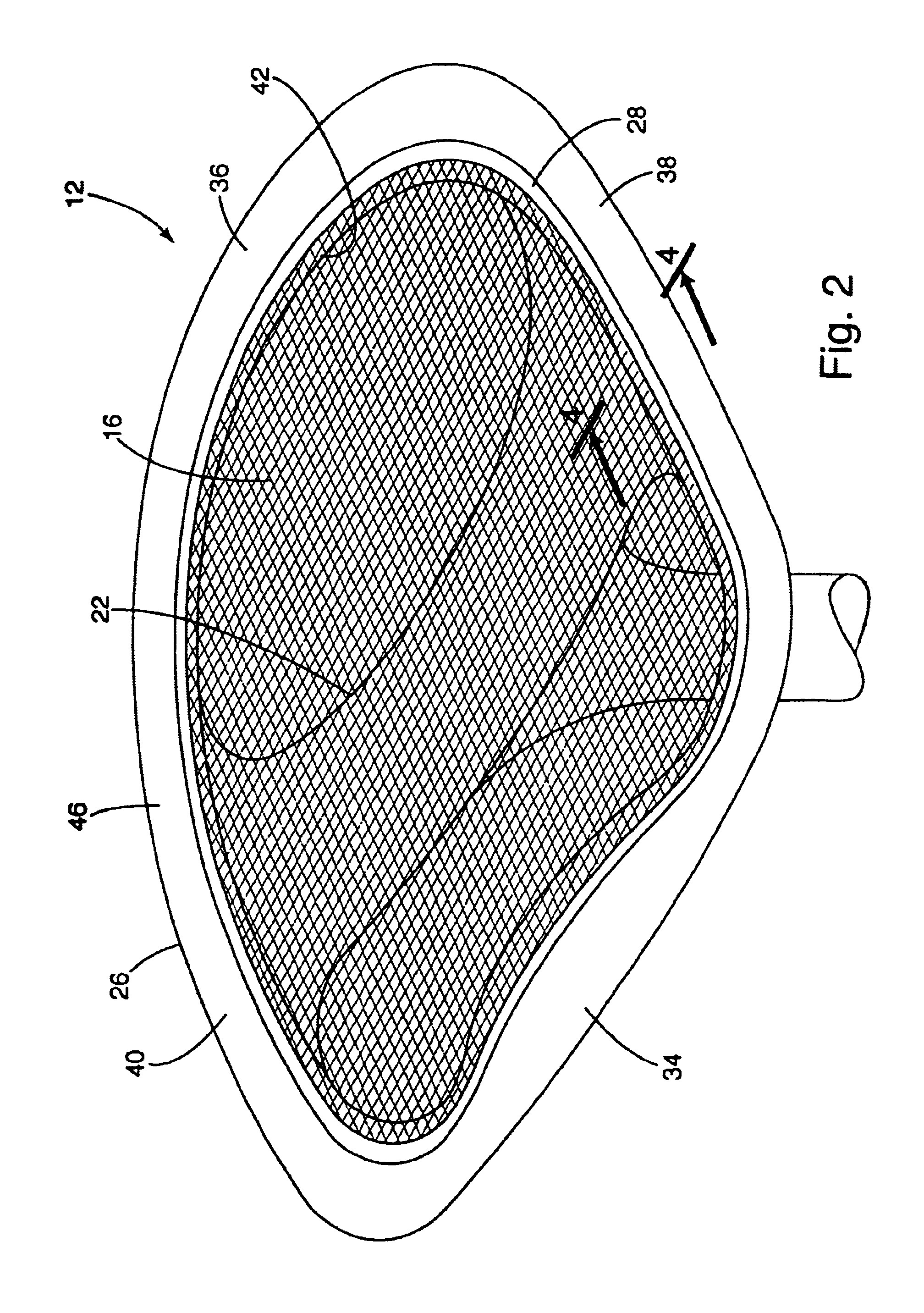
[0054]An office chair manufactured in accordance with a preferred embodiment of the present invention is shown in FIG. 1, and generally designated 10. The office chai...


PUM

PropertyMeasurementUnit
flexibleaaaaaaaaaa
cross-sectional areasaaaaaaaaaa
strengthaaaaaaaaaa

Abstract

An attachment structure for a load-bearing fabric including an expandable carrier secured to an un-stretched load-bearing fabric. To attach the carrier to a support frame, the carrier and fabric are stretched together to desired shape and secured to the frame. An indexing system registers the carrier and frame and optionally stretches the fabric a predetermined amount. The carrier and frame can include a lip that flexes in one direction and maintains the fabric in a stretched condition in another. A tool that joins the carrier and frame generally includes a drive roller and a primary roller adapted to move toward one another and join a carrier and the support frame disposed therebetween. The tool may include alignment rollers near the primary and drive rollers to track along and align the carrier and frame.

Description

[0001]This application is a continuation-in-part of U.S. application Ser. No. 10 / 342,602, filed Jan. 15, 2003 which is a division of U.S. application Ser. No. 09 / 666,624, filed Sep. 20, 2000 (now U.S. Pat. No. 6,540,950).BACKGROUND OF THE INVENTION[0002]The present invention relates to load-bearing fabric, and more particularly to components, tools and methods for securing a load-bearing fabric to a support structure.[0003]The use of load-bearing fabrics continues to grow dramatically in various industries, including the automotive, office and home seating industries. The term “load-bearing fabric” is commonly used to refer to a class of high strength, highly durable textiles that are typically woven from elastomeric monofilaments and conventional yarns. Some of today's load-bearing fabrics have greater strength and durability characteristics than spring steel and other conventional load bearing materials. In addition to their strength and durability characteristics, load-bearing fa...

Claims


Application Information

Patent Timeline
Patent Type & Authority Patents(United States)
IPC IPC(8): A47C7/22A47C7/28A47C31/02A47C7/02A47C31/00A47C7/00B29C45/14
CPCA47C7/282A47C31/02B29C45/14065B29C45/14336B29K2713/00Y10T29/48Y10T29/4987Y10T29/481Y10T29/486Y10T29/49876B29L2031/443
Inventor COFFIELD, TIMOTHY P.
Owner ILLINOIS TOOL WORKS INC
Why Eureka
Try Eureka