Trough reflectors for solar energy collectors

Inactive Publication Date: 2008-12-18
MIRALITE
View PDF26 Cites 119 Cited by
  • Summary
  • Abstract
  • Description
  • Claims
  • Application Information

AI Technical Summary

Benefits of technology

[0020]The primary objective of the present invention to provide a simple and effective method of applying an edge correction mom

Problems solved by technology

Such a sheet is generally flexible and will not maintain a specific profile unless it is constrained to have that profile, for example, by supports on which the sheet is placed.
The same problem exists when a number of thin reflective sheets are place

Method used


Image

  • Trough reflectors for solar energy collectors
  • Trough reflectors for solar energy collectors
  • Trough reflectors for solar energy collectors

Examples


Embodiment Construction

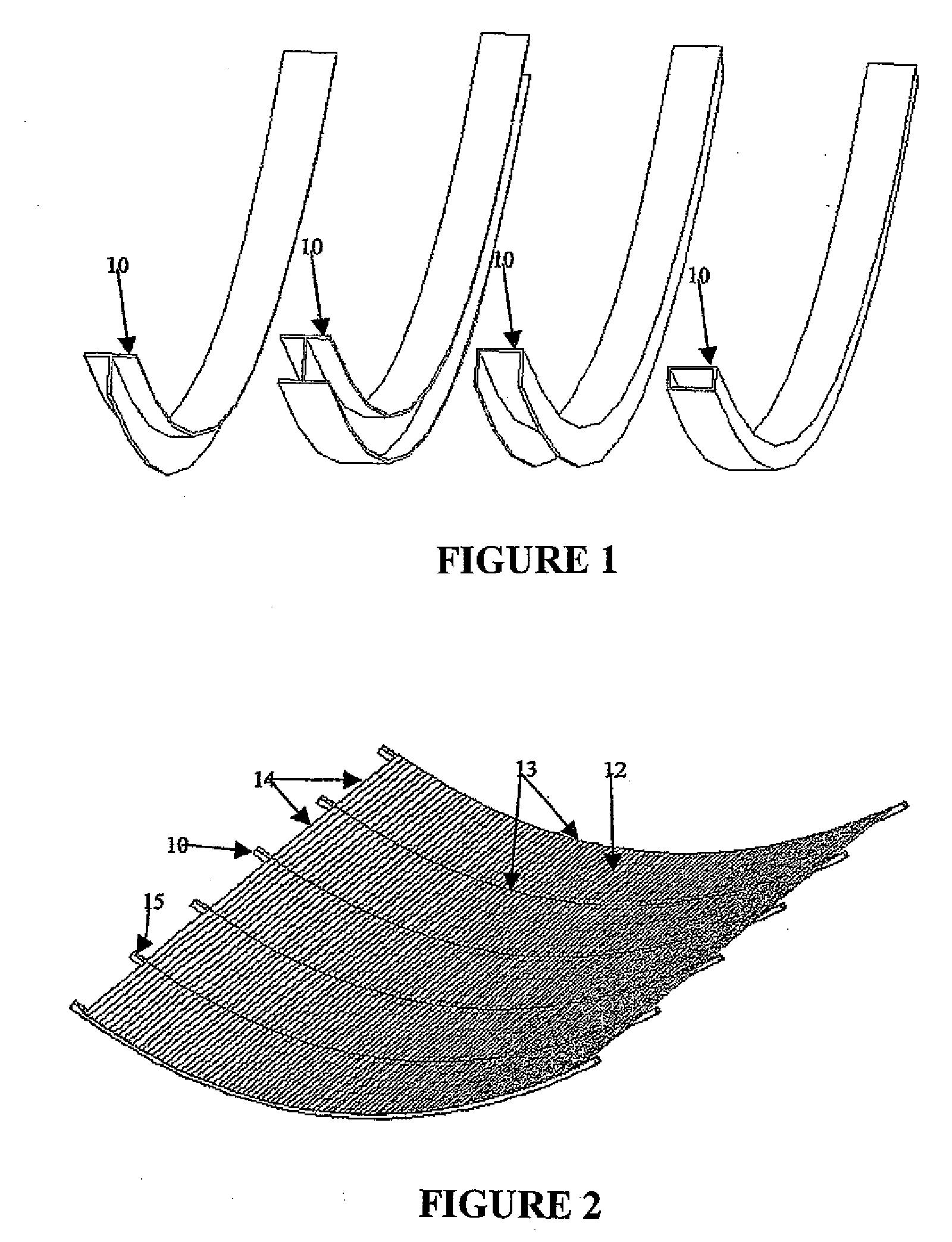
[0110]A trough reflector constructed in accordance with the first aspect of the present invention has ribs which have been pre-formed to have a parabolic upper surface profile. Such ribs may comprise ribs that have been worked to have a parabolic upper surface, or they may be constructed from thick or thin panels of metal, of a suitable plastics material, or of another suitable material. (A similar “non-rod” rib construction is shown in the aforementioned specifications of U.S. Pat. Nos. 4,390,241 and 4,820,033.) A rib which supports a reflective surface may also be formed by pressing tabs (which follow a parabolic curve) from thin metal panels, and supporting the reflective surface between the tabs, (Such a pressed-tab construction is illustrated in the aforementioned WIPO Publication No, WO 03 / 022578.) Alternatively, the tabs may be small pieces of a suitable material attached to a panel (such small pieces in this specification will be termed ‘tabs’).

[0111]At least one reflecting ...


PUM

PropertyMeasurementUnit
Forceaaaaaaaaaa
Distanceaaaaaaaaaa
Reflectionaaaaaaaaaa

Abstract

A trough reflector for solar energy collection is constructed from transverse ribs which support a reflective surface. Side edge support rails mounted on ends of the ribs support linear edges of the reflective surface. The edge support rails have a channel-like construction with an inner flange member which is in contact with a top of the reflective surface, and a lip member extending from an outer flange member. The edge region of the reflective surface rests on the lip member with the edge of the reflective surface in contact with the outer flange member. A turning moment is applied to the edge regions of the reflective surface to ensure that the entire reflective surface is parabolic. An arcuate profile of ribs of the trough reflector is converted into a parabolic profile by the application of a force to the ends of the ribs.

Description

TECHNICAL FIELD[0001]This invention concerns solar energy concentrators. More particularly, it concerns trough reflectors which are used to concentrate solar energy, and solar energy collectors which include such trough reflectors.PRELIMINARY NOTE[0002]In this specification, including the claims, “directional” terms (such as “top”, “bottom”, “side”, “underside”, “upper”, “lower”, “front”, “back”, “above”, “upwards”, “below”, “Vertical”, “horizontal” and the like) will be used in the sense that these terms would have with reference to an embodiment of the invention positioned as shown in FIG. 8 and FIG. 9 of the accompanying drawings.BACKGROUND TO THE INVENTION[0003]Trough reflectors or trough concentrators of solar energy have been known for a considerable time. For example, a trough reflector is described in the paper by Frank Shuman, presented to the Manchester Association of Engineers on 14 Mar. 1914, and published in the Proceedings of the Manchester Association of Engineers, (D...

Claims


Application Information

Patent Timeline
IPC IPC(8): F24J2/12B23P11/00B23P15/26G02B5/10F24S23/71
CPCF24J2/145F24J2/24F24J2/52F24J2/541F24J2002/5286Y10T29/49883Y02E10/44Y02E10/45Y02E10/47Y10T29/49963Y10T29/49355F24J2002/5475F24S25/00F24S2025/017F24S23/74F24S23/745F24S30/425F24S2030/14F24S10/70Y02E10/40
Inventor JOHNSTON, GLEN
Owner MIRALITE
Why Eureka
Try Eureka