Immiscible liquid separator for marine vessels

a liquid separator and marine technology, applied in the field of apparatus, can solve the problems of inability to operate, degrade the operation of the separator unit, and blockage, and achieve the effect of efficient expulsion

Active Publication Date: 2018-07-31
GOSLYN GENERAL LLC
View PDF13 Cites 4 Cited by
  • Summary
  • Abstract
  • Description
  • Claims
  • Application Information

AI Technical Summary

Benefits of technology

[0009]In accordance with the principles and concepts of the invention, disclosed is an immiscible liquid separator that is adapted for operation at different angles, such as experienced on ships and other ocean-going vessels. According to a feature of the invention, rather than constructing a separator with an oil discharge outlet spaced from a planar-type water weir, the oil discharge outlet of the invention is a cylindrical oil stack that is surrounded by a cylindrical water weir. With this arrangement, the separated water will raise the level of the separated oil within the separator enclosure and both will be efficiently expelled out of respective outlets, independent of the angle of tilt of the separator.
[0011]A further feature of the invention is the utilization of a ball float type valve that controls the type of liquids that are coupled to the cylindrical oil stack. The ball of the valve is constructed with a material that is buoyant to water, but is not buoyant to oil, whereby when separated water attempts to be coupled to the oil circuit of the cylindrical oil stack, it will be blocked. This prevents the inadvertent coupling of water to the oil discharge outlet.

Problems solved by technology

If the greases and fats solidify in the sewage system, a blockage can occur which is expensive to remediate.
If the separator is not level, then the weir can be tilted and the incoming waste liquid influent does not lift the floating oil in the vicinity of the release ball valve sufficiently to allow the oils to be discharged out of the ball valve.
Either of these results degrades the operation of the separator unit.
However, there are situations where this is not always possible.
For example, restaurants and food preparation facilities on ships and other marine vessels are themselves not maintained level, as the ship's pitch and roll motion causes all equipment mounted thereto to move accordingly.
As such, the ability to maximally separate the immiscible liquids with conventional separators is compromised.
Moreover, when ships equipped with holding tanks do empty the waste material at shore facilities, the costs can be significant, as shore facilities must be available to then accept and process the wastes and dispose of the same in an environmentally safe manner.
At this point, the fat, oil and grease content of the waste material have degraded to a point where they are not suitable for recycling.

Method used


Image

  • Immiscible liquid separator for marine vessels
  • Immiscible liquid separator for marine vessels
  • Immiscible liquid separator for marine vessels

Examples


Embodiment Construction

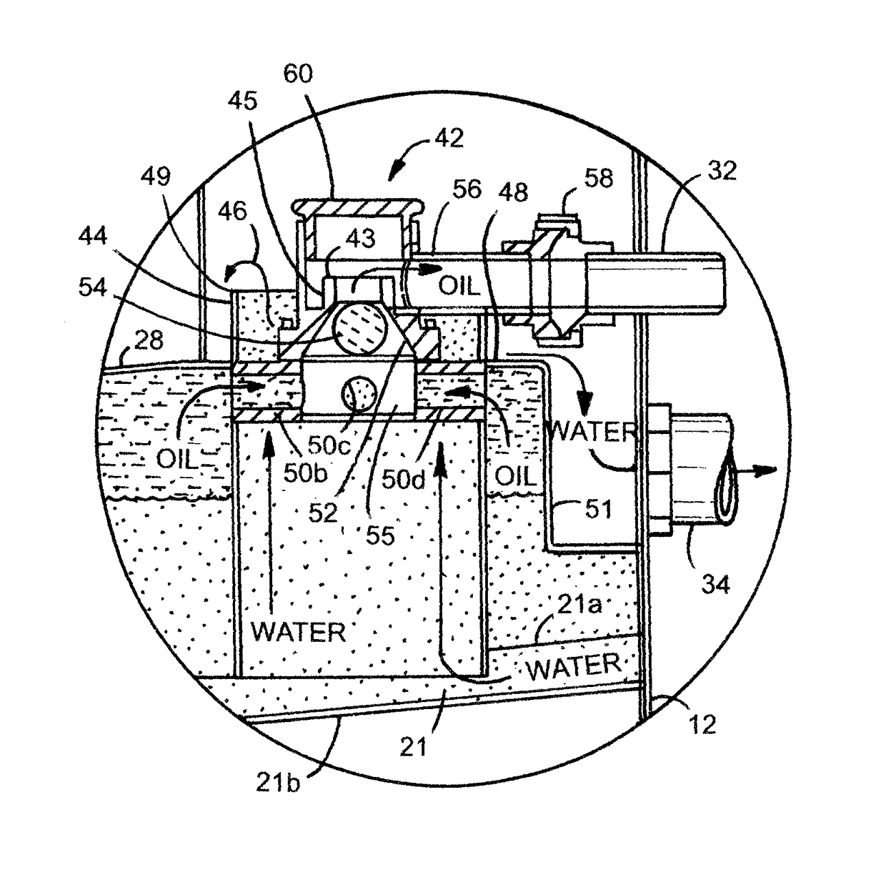
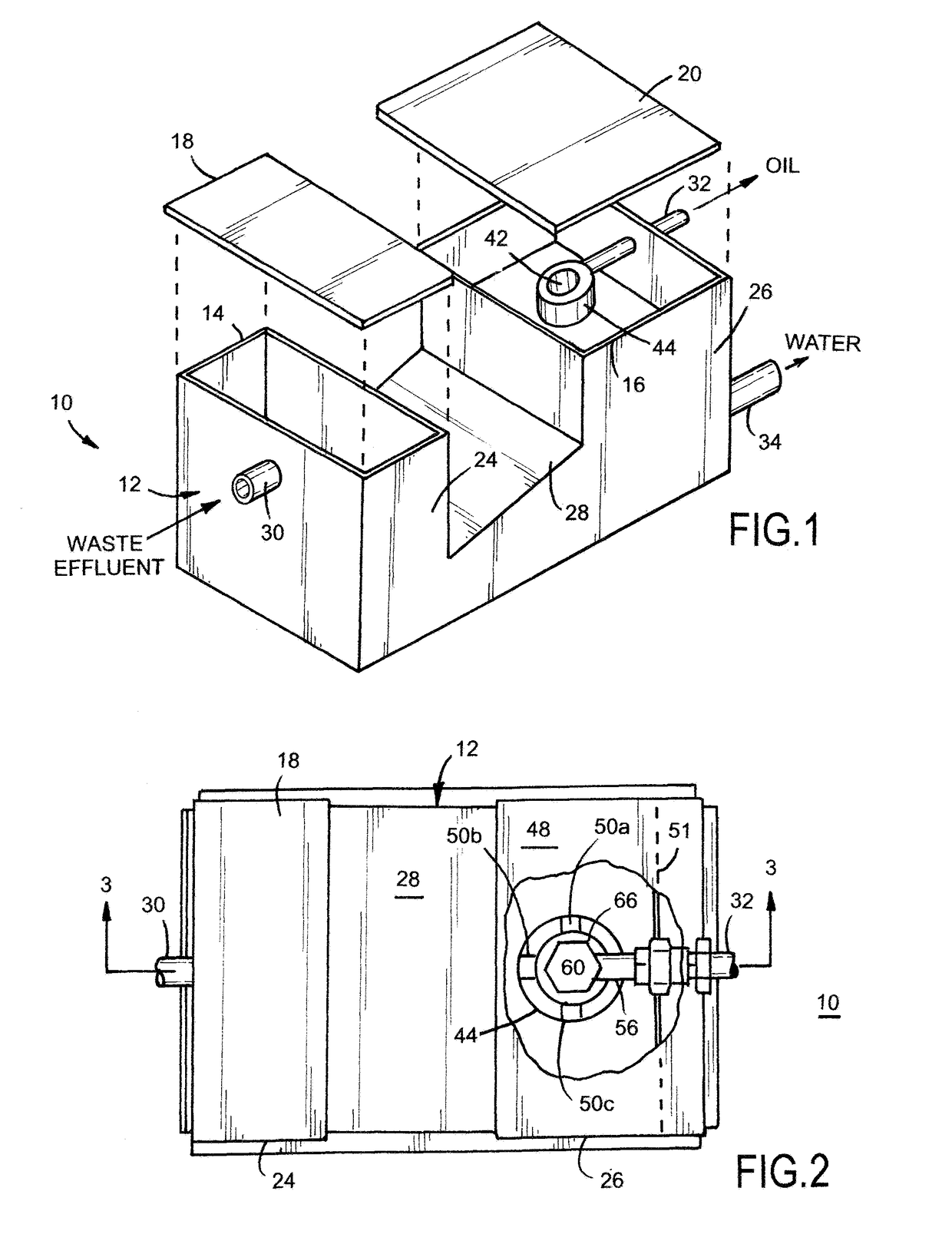
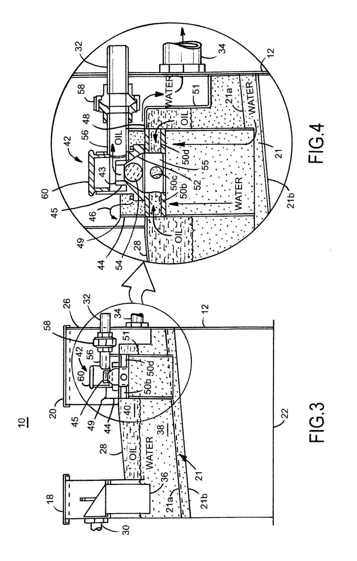
[0025]With reference to FIGS. 1-4, there is illustrated an immiscible liquid separator system adapted for marine use, i.e., use on a marine vessel, or the like. The illustrated immiscible liquid marine separator unit 10 is constructed according to one embodiment of the invention. The immiscible liquid separator 10 is adapted for separating immiscible liquids, such as oils and water commonly produced in food processing facilities. The immiscible liquid separator 10 comprises an enclosure 12 having two open tops 14 and 16 covered by respective lids 18 and 20. The lids 18 and 20 are shoe-box type lids sealed to the rims of the open tops 14 and 16 by neoprene seals. The lids 18 and 20 can be fastened to the enclosure 12 by clips or other quick release fasteners. The immiscible liquid separator 10 also includes a planar bottom 22 adapted for resting on a floor of the vessel or ship. The various side, bottom and lids can be constructed of stainless steel, synthetic or other suitable mater...


PUM

PropertyMeasurementUnit
specific gravityaaaaaaaaaa

Abstract

An immiscible liquid separator for maintaining a desired liquid relationship between an oil spillover and a water spillover irrespective of a tilt angle of the separator. The use of the separator is thus well adapted for use on ships and the like. The separator includes a cylindrical weir having an open top over which separated water spills when waste liquid is drained into the separator. The separator also includes a cylindrical oil stack having an open top over which separated oil spills when waste liquid is drained into the separator. The cylindrical oil stack is located within the cylindrical water weir, thus allowing the separator to function as desired independent of the angle of tilt of the separator.

Description

RELATED APPLICATION[0001]This non-provisional patent application claims the benefit of pending U.S. provisional application filed Aug. 21, 2015, Ser. No. 62 / 283,120.TECHNICAL FIELD OF THE INVENTION[0002]The present invention relates in general to apparatus that separates immiscible liquids, and more particularly to water / oil separation apparatus.BACKGROUND OF THE INVENTION[0003]In several industries, and in particular the food industry, there is a need to separate liquid greases, fats and oils from waste water prior to passing the water to the sewage system. The waste water could be, for example, discharged from a washing device for cleaning dinnerware and cooking utensils. If the greases and fats solidify in the sewage system, a blockage can occur which is expensive to remediate.[0004]It has been found that the liquid wastes from kitchens are often immiscible mixtures of water and oils. As is well known, a first immiscible liquid of one specific gravity will float on a second immis...

Claims


Application Information

Patent Timeline
Patent Type & Authority Patents(United States)
IPC IPC(8): B01D17/032C02F1/40B01D17/02C02F101/32C02F103/32
CPCC02F1/40B01D17/0208B01D17/0214C02F2103/32C02F2101/32C02F2201/005B01D17/0211
Inventor SOWERBY, GILES S.SOWERBY, JOHN C.
Owner GOSLYN GENERAL LLC
Why Eureka
Try Eureka