Static pose fixture

a fixture and static technology, applied in the field of static pose fixtures, can solve problems such as loose accuracy, magnetic system, and experience distortion, and achieve the effects of accurate repeatable measurements, accurate repeatable subject data, and accurate depiction of subjects

Inactive Publication Date: 2005-08-02
TOPGOLF CALLAWAY BRANDS CORP
View PDF8 Cites 2 Cited by
  • Summary
  • Abstract
  • Description
  • Claims
  • Application Information

AI Technical Summary

Benefits of technology

[0014]Furthermore, the present invention enables a technician to make accurate repeatable measurements and eliminates a vast number of steps previously required to perform the measurements and removes variables that typically lead to inaccuracy in designing computer generated models used in motion capture. By identifying and measuring body plate locations of the subject while in the static pose fixture, the static pose fixture also provides a means to automatically position and orient motion agents corresponding to the body plate locations on the model for achieving accurate repeatable subject data.
[0015]Moreover, if a body plate moves during the modeling process as often happens, the static pose fixture provides a means to rapidly and automatically re-position the subject's body plate location for measuring segment length, body angle or body orientation, whereas without the static pose fixture, the entire marker orienting process needs to be repeated from the beginning.

Problems solved by technology

Since golf clubs are typically constructed of metal or metal parts, magnetic systems, which may loose accuracy when metal objects are near by, may experience some distortion during a golf swing motion measurement.
Some human modeling software allows the user to measure body segments and input values, which can increase accuracy but is relatively time consuming.
However, the process of sizing and orienting the model in the point cloud is time consuming and inaccurate.
Because the orientation of each limb in space is estimated by the operator, it is subject to variation and inaccuracy.
As motion capture data is used to drive the model, this inaccuracy will cause the wrist to be driven to a location that is offset from the measured location.
When modeling a golf swing, even slight inaccuracy in the wrists can lead to large inaccuracy in the location of the club head, rendering the model far less useful.
Additionally, if any of the markers move with respect to the subject once the model generation is complete, the process must be repeated from the beginning or further inaccuracy will result.

Method used


Image

  • Static pose fixture
  • Static pose fixture
  • Static pose fixture

Examples


Embodiment Construction

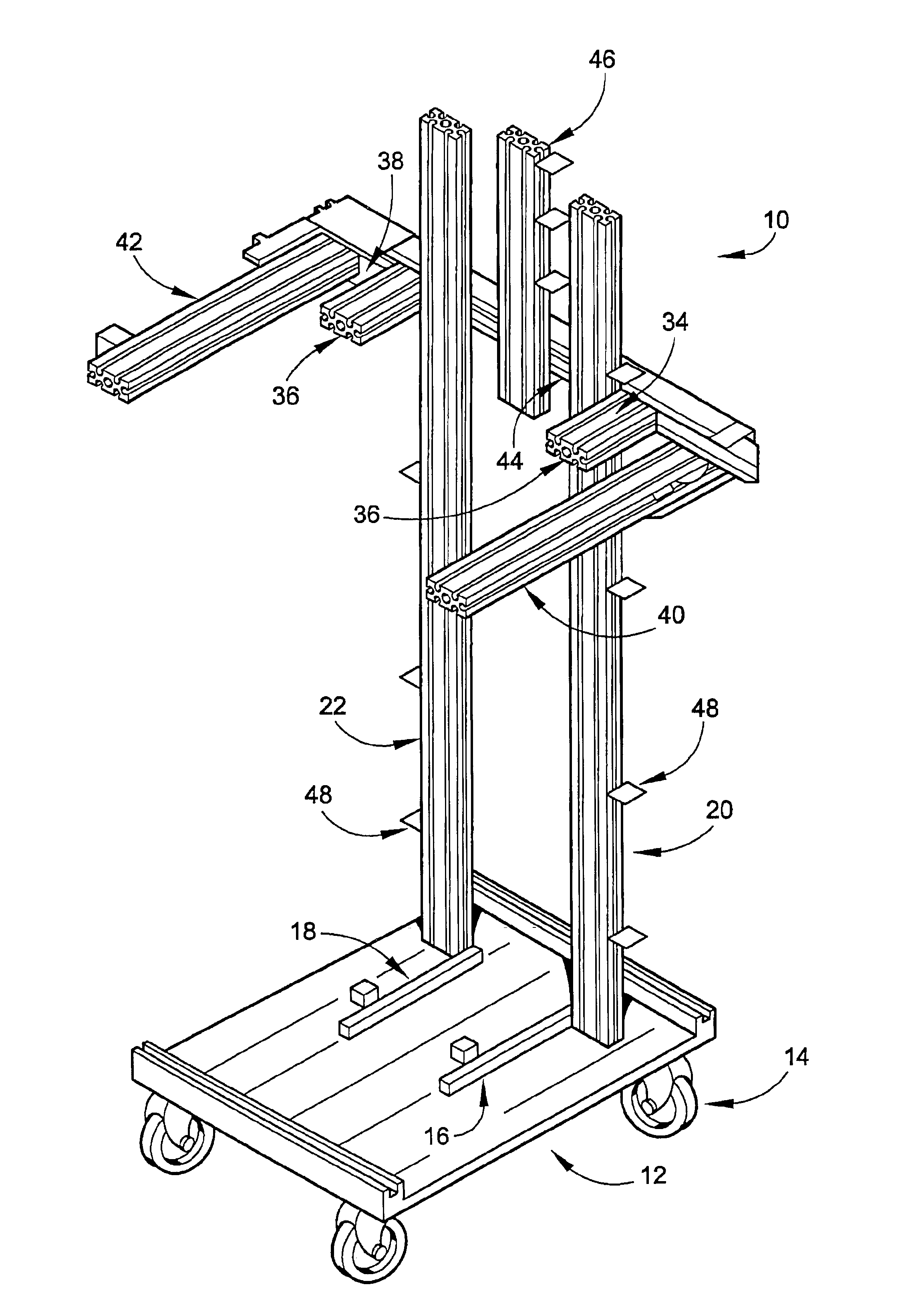
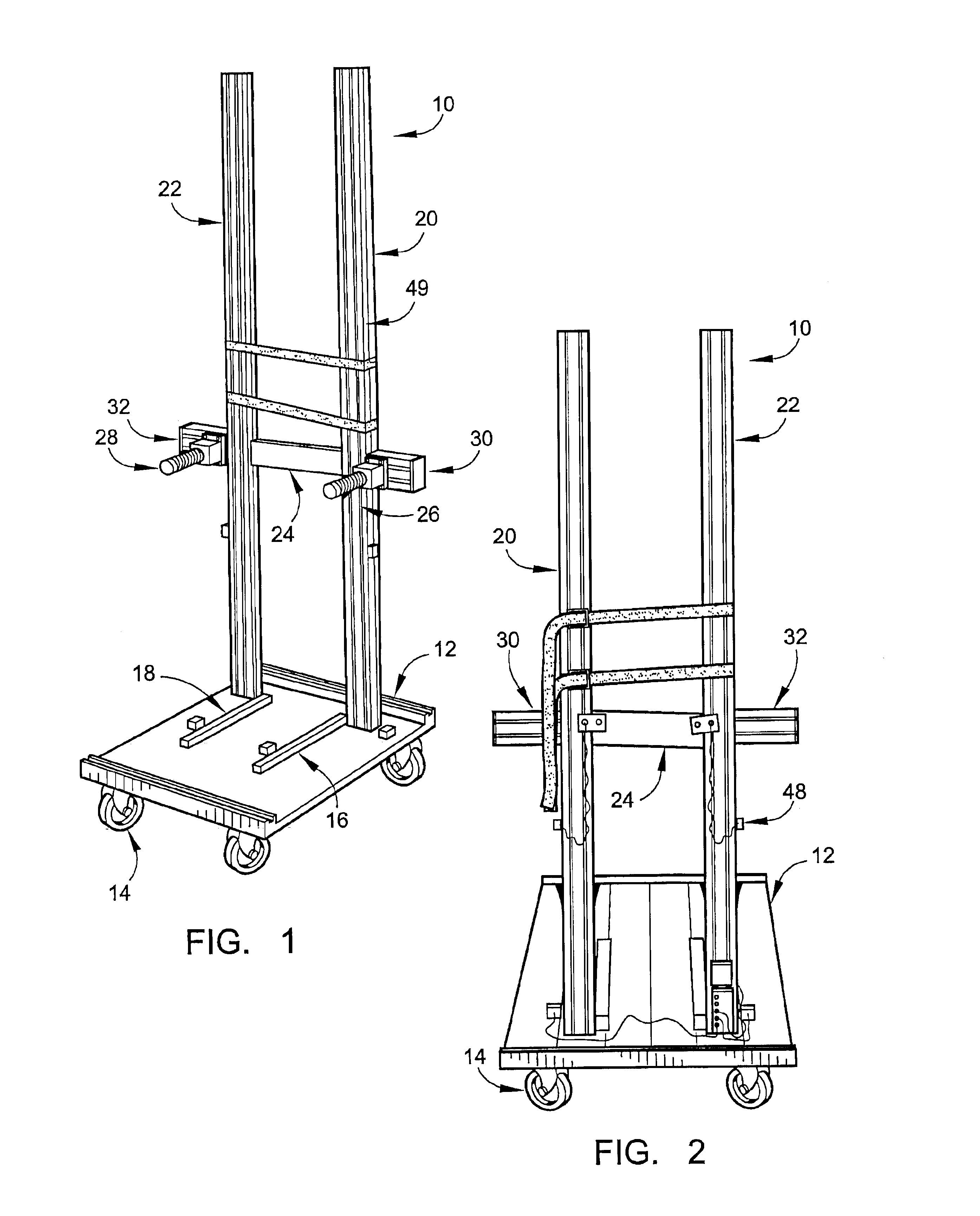
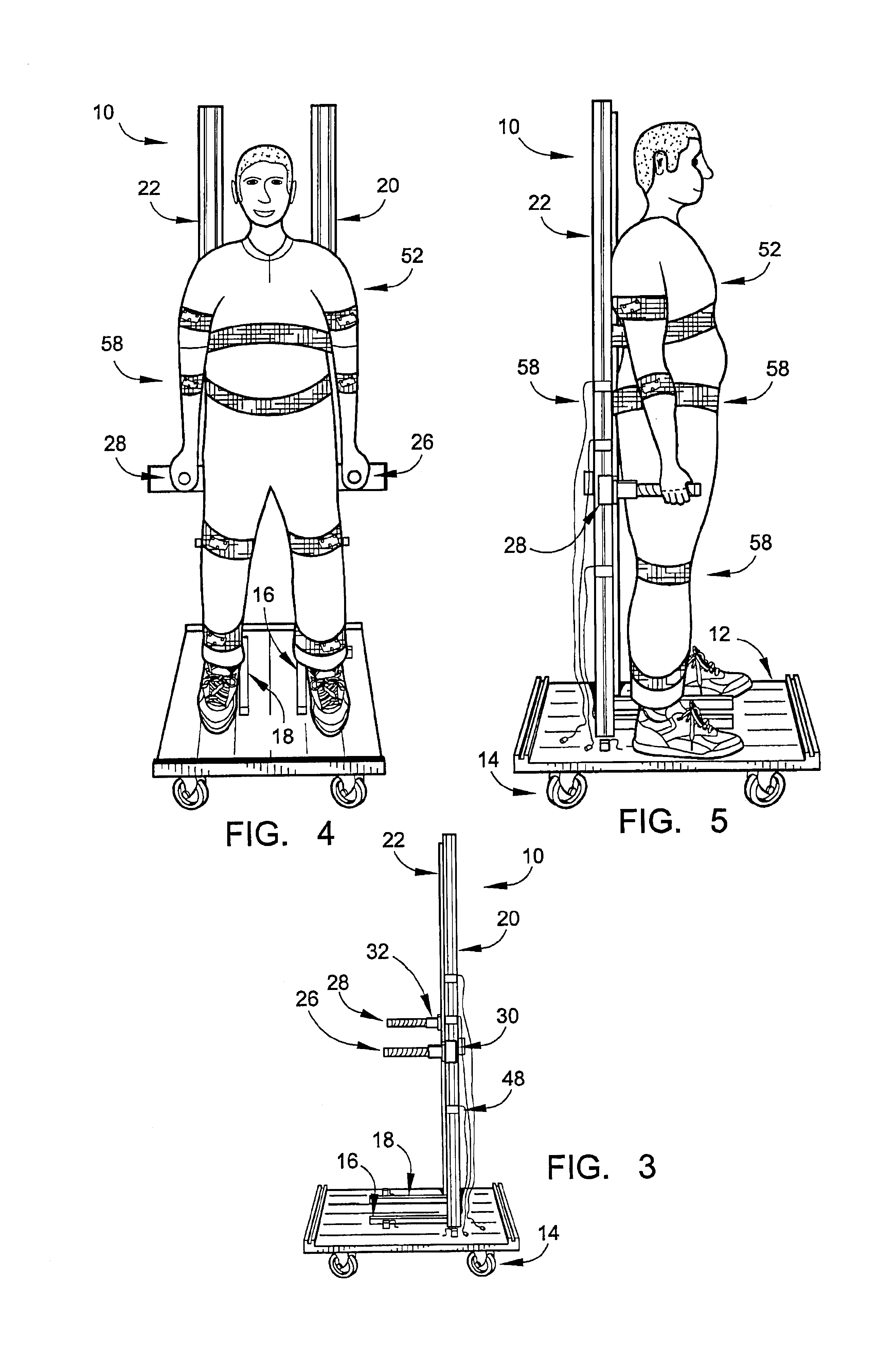
[0032]As illustrated in FIG. 1, a static pose fixture for measuring the size of a motion capture subject 52 is generally designated 10. The static pose fixture 10 of the present invention includes a base 12, first and second foot alignment struts 16 and 18, first and second vertical struts 20 and 22, first and second grips 26 and 28 and first and second slider struts 30 and 32.

[0033]The base 12 is preferably substantially flat. The base 12 preferably has a plurality of wheels 14, to provide the fixture 10 with mobility.

[0034]As illustrated in FIGS. 1-3, first and second foot alignment struts 16 and 18 for placement of a right and left foot of a subject 52 are located on the upper exterior portion of the base 12. The first and second foot alignment struts 16 and 18 are preferably placed at least 4 inches from the rear portion of the base 12. The distance d between the first foot alignment strut 16 and the second foot alignment strut 18 is preferably between 10 inches and 18 inches, m...


PUM


Abstract

The present invention relates to a static pose fixture (10) used for measuring a subject (42) that is the object of a motion capture system. The static pose fixture (10) provides a means for holding the subject (52) in a static position by using various struts in order to automate the sizing of a computer generated model or to position and orient markers with respect to the model.

Description

CROSS REFERENCE TO RELATED APPLICATIONS[0001]The present application is a divisional application of U.S. patent application Ser. No. 10 / 064,739, filed on Aug. 12, 2002, now U.S. Pat. No. 6,702,691.FEDERAL RESEARCH STATEMENT[0002][Not Applicable]BACKGROUND OF INVENTION[0003]1. Field of the Invention[0004]The present invention relates to a static pose fixture that is utilized in motion capture systems. More specifically, the present invention relates to a static pose fixture utilized to measure geometry and body plate marker locations of a subject for preparation of a motion capture model during a golf swing.[0005]2. Description of the Related Art[0006]Motion Capture is used to measure the position and or orientation of any object, usually at multiple points in time. There are four main categories of motion capture devices, mechanical, magnetic, passive optical, and active optical. An example of a mechanical device is the Cyberglove®. A mechanical device measures the orientation of ri...

Claims


Application Information

Patent Timeline
Patent Type & Authority Patents(United States)
IPC IPC(8): A63B69/36A61B5/103A61B5/107A61B5/117A63B53/06A63B53/16A63B71/02
CPCA61B5/1072A61B5/4561A63B69/3608A63B69/0059A61B5/4528A63B2071/0694A63B2209/10A63B2225/09A63B2071/025
Inventor ERICKSON, MATTHEW J.CHERVENY, PATRICK M.GILE, ADAM S.
Owner TOPGOLF CALLAWAY BRANDS CORP
Why Eureka
Try Eureka