Distance to Golf Cup Measuring Accessory

a technology for distance to golf cups and measuring accessories, applied in golf, golfing accessories, sport apparatus, etc., can solve problems such as errors introduced into measurements, and achieve the effect of accurate repeatable measurements

Inactive Publication Date: 2013-06-13
ROARK DAVE +1
View PDF26 Cites 3 Cited by
  • Summary
  • Abstract
  • Description
  • Claims
  • Application Information

AI Technical Summary

Benefits of technology

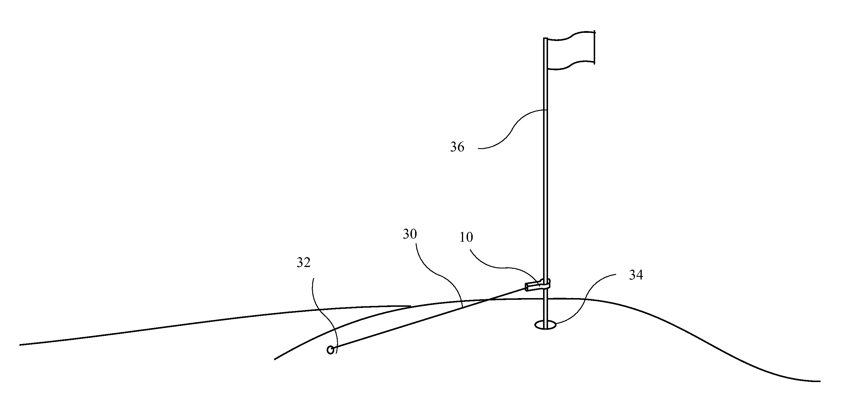
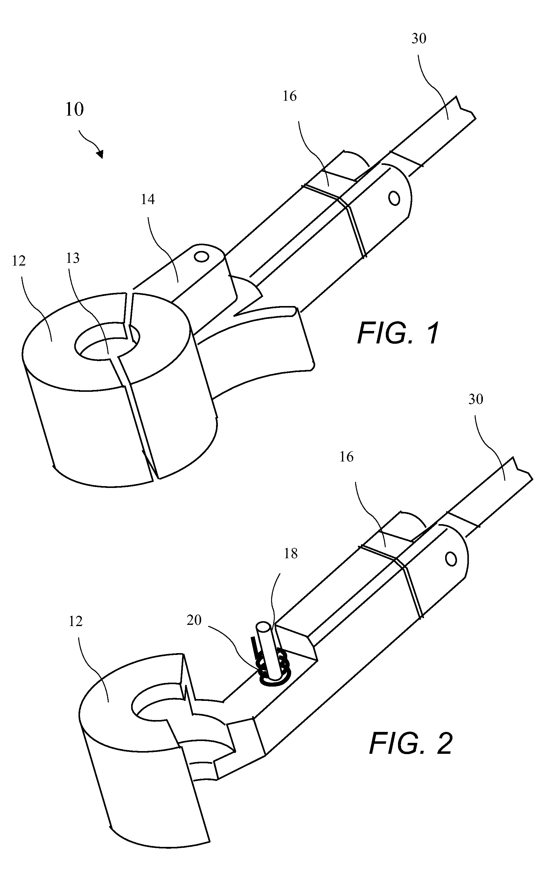
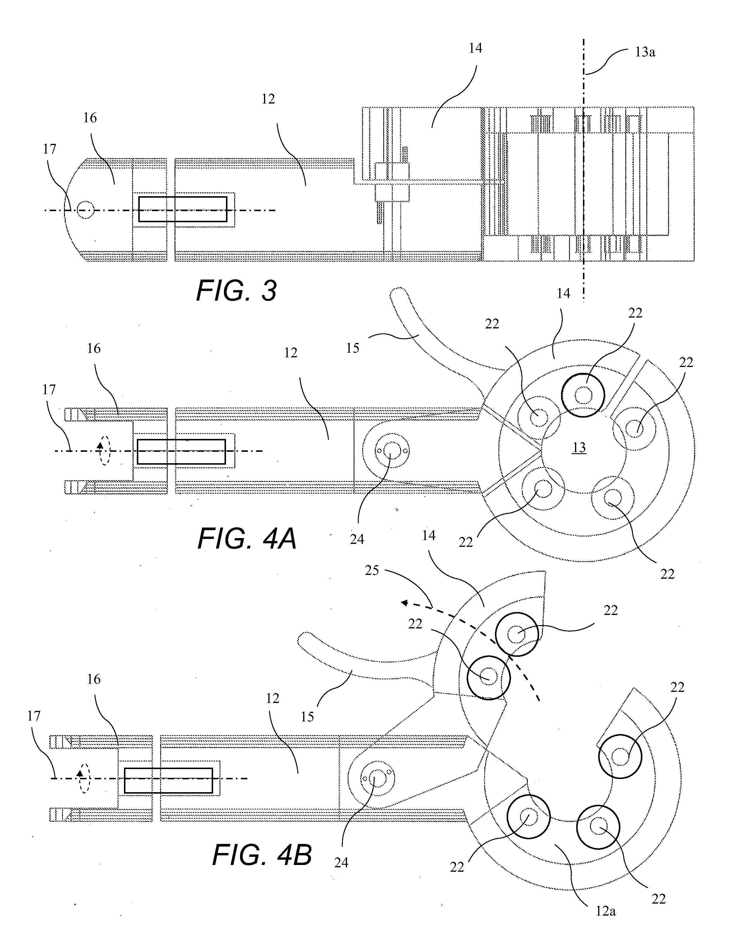
[0004]The present invention addresses the above and other needs by providing a tape measure which is attached to an accessory attached to a flag pole residing in a golf course hole. The accessory includes a mouth openable to engage the flag pole. Once the mouth is closed, the pole resides in a throat surrounded by a plurality of rollers residing co-axial with the pole. The rollers allow the accessory to freely rotate on the flag pole, but include a non-slip outer surface to prevent the accessory from sliding on the pole. Tape is drawn from the tape measure attached to a measuring tape attachment feature to measure the distance to a golf ball, and the accessory freely rotates on the flag pole to provide accurate repeatable measurements. The tape measure is preferably attached to an axially rotating measuring tape attachment feature.

Problems solved by technology

Presently, the distance from the ball to the hole can only be measured by two players using a tape measure, using golf clubs, using the flag pole, or stepping off the distance, and when two balls are at similar distances from the hole, errors introduced into the measurements may produce a wrong result.

Method used


Image

  • Distance to Golf Cup Measuring Accessory
  • Distance to Golf Cup Measuring Accessory
  • Distance to Golf Cup Measuring Accessory

Examples


second embodiment

[0034]A top view of the distance to golf hole measuring accessory 10a according to the present invention with a closed jaw 14a is shown in FIG. 10A and a top view of the distance to golf hole measuring accessory 10a with an open jaw 14a is shown in FIG. 10B. The distance to golf hole measuring accessory 10a is functionally similar to the distance to golf hole measuring accessory 10.

[0035]A top view of the distance to golf hole measuring accessory 10a with a side plate 40 (see FIG. 10A and 10B) removed and the closed jaw is shown in FIG. 11A and a top view of the distance to golf hole measuring accessory 10a with the side plate removed and the open jaw is shown in FIG. 11B. When the jaw 14a is closed, a narrowing end 50 is seated in a recess 48 in a seat 42, and a spring 44 applies force to the seat 42. The cooperation of the narrowing end 50 and the recess 48 holds the jaw 14a in the closed position. When the jaw 14a is pivoted about a jaw pivot 56 along arc 52, the narrowing end 50...

third embodiment

[0037]A top view of the distance to golf hole measuring accessory 10b according to the present invention with the side plate removed and the closed jaw is shown in FIG. 13A and a top view of the distance to golf hole measuring accessory 10b with the side plate removed and the open jaw is shown in FIG. 13B. The distance to golf hole measuring accessory 10b includes a flat spring 60 having a fixed end 60a fixed inside the handle 12 and a free end 60b opposite the fixed end and resting against a lever end 62 of a third jaw 14b. The flat spring 60 applies closing force to the jaw 14b to hold the jaw 14b on the flag pole 36.

[0038]An distance to golf hole measuring accessory 10′ having lips 70 for holding a measuring tape 72 is shown in FIG. 14. The distance to golf hole measuring accessory 10′ may include any features of the distance to golf hole measuring accessories 10, 10a, or 10b.


PUM


Abstract

A tape measure is attached to an accessory attached to a flag pole residing in a golf course hole. The accessory includes a mouth openable to engage the flag pole. Once the mouth is closed, the pole resides in a throat surrounded by a plurality of rollers residing co-axial with the pole. The rollers allow the accessory to freely rotate on the flag pole, but include a non-slip outer surface to prevent the accessory from sliding on the pole. Tape is drawn from the tape measure attached to a measuring tape attachment feature to measure the distance to a golf ball, and the accessory freely rotates on the flag pole to provide accurate repeatable measurements. The tape measure is preferably attached to an axially rotating measuring tape attachment feature.

Description

[0001]The present application claims the priority of US Provisional Patent Application Ser. No. 61 / 568,580 filed Dec. 8, 2011, which application is incorporated in its entirety herein by reference.BACKGROUND OF THE INVENTION[0002]The present invention relates to determining the distance from a golf ball location to a hole and in particular to an accessory which attaches to a flag pole facilitating the measurement.[0003]The game of golf is widely enjoyed around the world. Golf is regularly played in tournament, casual play, and practice. One common activity is precisely measuring the distance from a ball to the hole. Such measuring is done to determine the order of play, and in some events, to award prizes for the closest approach shot. Presently, the distance from the ball to the hole can only be measured by two players using a tape measure, using golf clubs, using the flag pole, or stepping off the distance, and when two balls are at similar distances from the hole, errors introduc...

Claims


Application Information

Patent Timeline
Patent Type & Authority Applications(United States)
IPC IPC(8): A63B57/00
CPCA63B67/068A63B2220/20A63B2069/3602A63B69/36
Inventor ROARK, DAVEROGERS, JAMES A.
Owner ROARK DAVE
Why Eureka
Try Eureka