Work function calibration of a non-contact voltage sensor

a non-contact voltage sensor and work function technology, applied in the field of methods and systems, can solve the problems of difficult to create a surface with a known surface potential, difficult to accurately determine the surface potential, and relatively difficult to handle and automate in a factory environment, so as to improve the capability of measuring and improve the accuracy of the surface potential

Inactive Publication Date: 2017-04-18
QCEPT INVESTMENTS LLC
View PDF8 Cites 0 Cited by
  • Summary
  • Abstract
  • Description
  • Claims
  • Application Information

AI Technical Summary

Benefits of technology

[0018]The system and methods described in this invention readily provide an enhanced application of a noncontact voltage sensor for making accurate and repeatable measurements of the electrical potential, or work function, of surfaces. The invention includes an enhanced capability for measuring and monitoring the surface potential of a noncontact voltage sensor probe tip. It also provides the ability to independently detect changes in the electrical potentials of the noncontact voltage sensor probe tip and various reference surfaces over time. The ability to accurately determine the surface potential of the noncontact voltage sensor probe tip allows the sensor to be used to measure the absolute potentials of other surfaces. This capability is useful for detecting changes in surface condition, including changes that result from surface contamination, charging of dielectric films on the surface, or changes in the work functions of films that may affect the performance of microelectronic devices.
[0021]The controlled environment can take many different forms. A typical controlled environment would include an enclosure with controls for maintaining one or more constant environmental characteristics such as temperature, humidity, cleanliness, and illumination. All of these factors have been shown to influence surface work function. The controlled environment could also include the ability to purge the area around the reference surfaces and reference probe tip with specific gasses, or to create a full or partial vacuum around the reference surfaces and reference probe tip. Gasses can be chosen to minimize potential chemical reactions between the environment and reference surfaces and reference probe tip. Filters can be used to process the atmosphere in the controlled environment to reduce particulates or remove organic or other contaminants. The controlled environment can include one or more of the above controls alone or in combination.
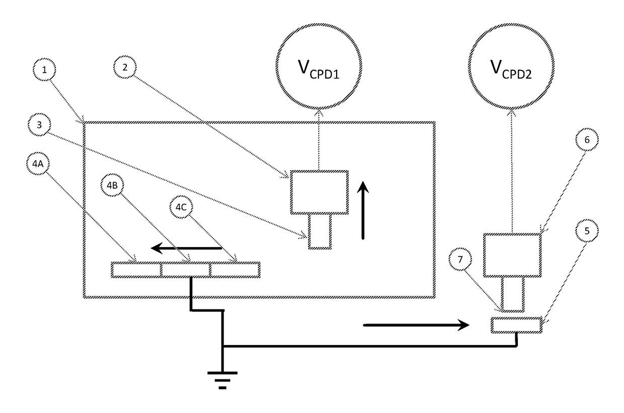
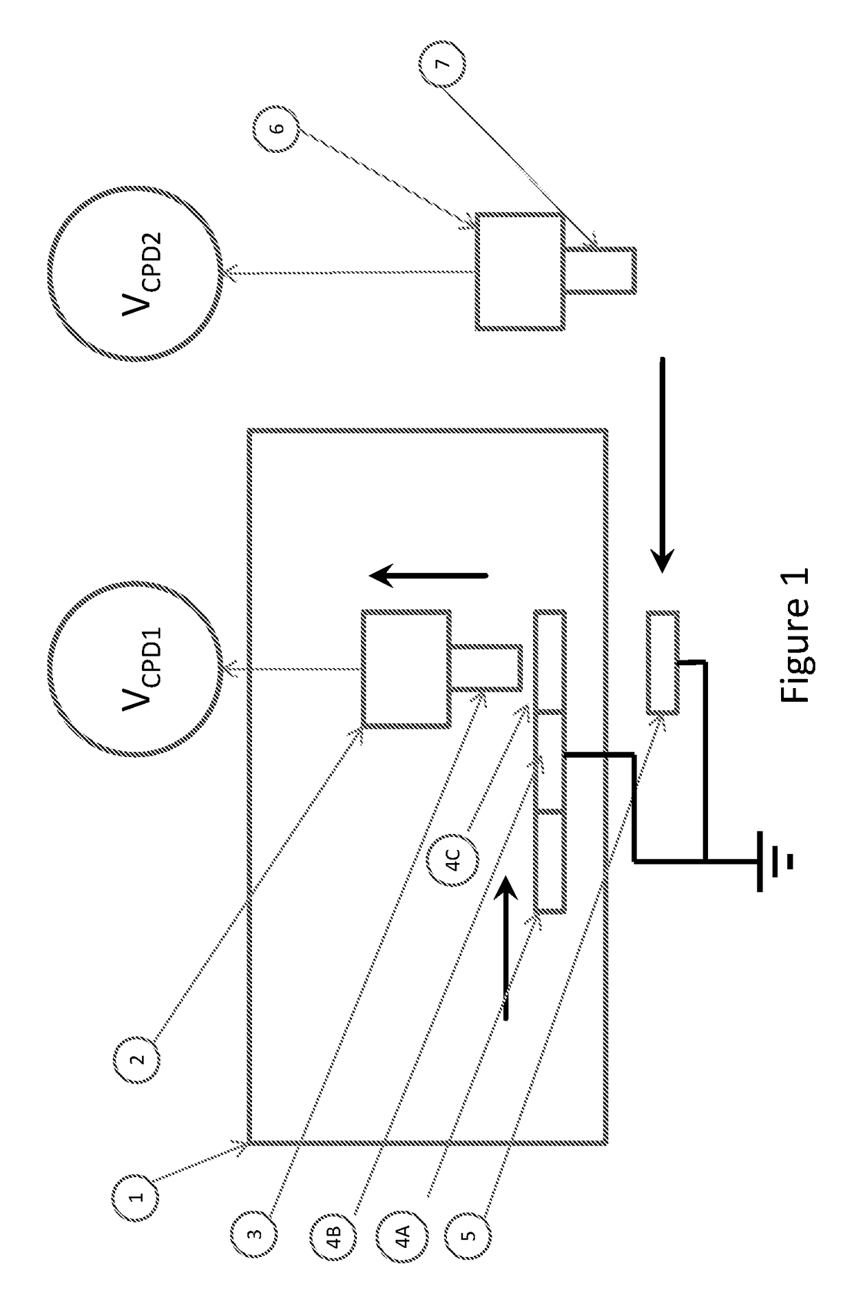
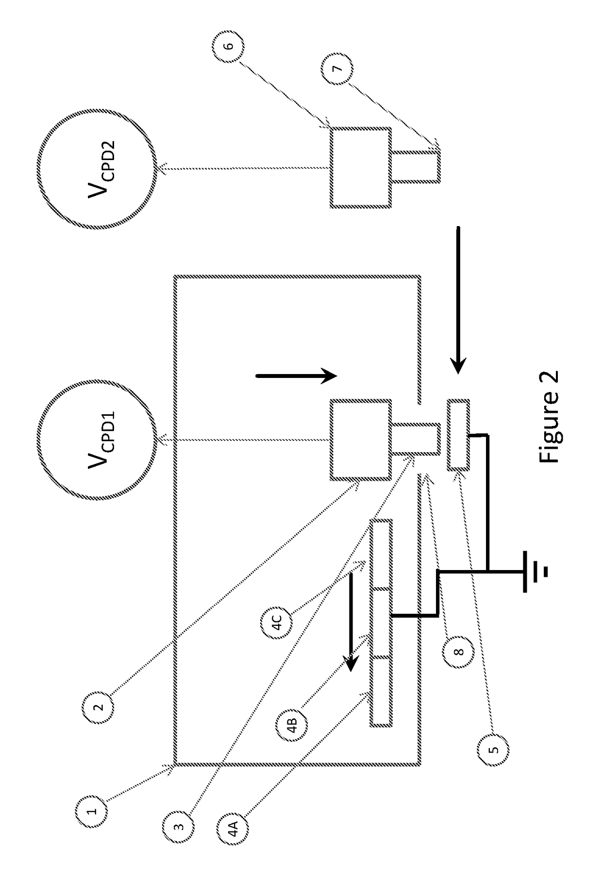
[0022]The important innovation of this invention is the inclusion of both reference surfaces and a reference noncontact voltage sensor probe tip in a controlled environment. The use of a reference probe tip provides two important benefits. The first benefit is that the actual reference surfaces do not need to be removed from the controlled environment in order to perform CPD measurements on them. Removing the reference surfaces from the controlled environment would expose the surfaces to a new environment. This could cause surface chemical reactions or adsorption that may cause the work functions and surface potentials of the surfaces to change. Once the surface is disturbed, the surface condition and surface potential could continue to change over a period of minutes, hours or even days. Maintaining reference surfaces with stable surface potentials is critical to the accurate monitoring of the nonreference noncontact voltage sensor probe tip work function, which is one of the purposes of this invention. Of course removing the reference sensor probe tip from the controlled environment may cause the work function and surface potential of the reference sensor probe tip to change. However, these changes tend to occur slowly over a period of minutes. As long as the surface potential of the reference sensor probe tip is stable over the time between CPD measurements on the reference surfaces in the controlled environment and the nonreference surface outside of the controlled environment, then the relative surface potentials of the reference and nonreference surfaces can be determined accurately. This time between CPD measurements inside and outside of the controlled environment is typically less than one minute. If the surface potential of the reference sensor probe tip changes slowly between subsequent calibrations, this will have no effect on the accuracy of the calibrations because the surface potential of the nonreference voltage sensor probe tip is always calibrated relative to the stable work functions of the reference surfaces.
[0023]The second benefit of using a reference noncontact voltage sensor is that it allows the CPD to be determined separately between the reference sensor probe tip and 1) the reference surfaces in the controlled environment, and 2) the nonreference noncontact voltage sensor probe tip. If the nonreference noncontact voltage sensor probe tip is used to directly measure the CPD of the reference surfaces, any change in the CPD value could be the result of a change in surface potential of the nonreference sensor probe tip, the reference surfaces, or both. There is no way to know for sure which surface is changing. The use of a reference noncontact voltage sensor allows independent CPD measurements that can be used to help identify the source of any change in CPD between the nonreference sensor probe tip and reference surfaces. For example, if the CPD between a reference surface and the reference sensor probe tip is stable over multiple measurements, but the CPD between the reference sensor probe tip and the nonreference sensor probe tip changes, then the change can be attributed to a change in the surface potential of the nonreference sensor probe tip. This is the most common situation because the nonreference sensor probe tip operates in an uncontrolled environment. If the surface potential of the nonreference noncontact voltage sensor probe tip changes, then the new surface potential of the nonreference sensor probe tip can be recalculated based on the CPD between the nonreference noncontact voltage sensor probe tip and a reference surface with stable surface potential. However, if the CPD between the reference sensor probe tip and a reference surface changes, but the CPD between the reference sensor probe tip and the nonreference sensor probe tip is stable, this could indicate a change in the surface potential of the reference surface, and would require recalibrating all surface potentials using a reference surface with a known surface potential, such as an electrolyte solution in contact with a liquid electrochemical half cell.

Problems solved by technology

One of the biggest challenges in making accurate and repeatable surface potential measurements using a noncontact voltage sensor is determining the surface potential of the sensor probe tip.
However, it is difficult to create a surface with a known surface potential in air.
However, liquid half cell references require periodic refilling, so they are relatively difficult to handle and automate in a factory environment.
For this reason, liquid half cell references are not well suited to frequent calibrations in an industrial environment.
Creating a solid reference surface with stable surface potential is a difficult problem.
As already mentioned, environmental factors can significantly affect the work function and electrical potential of a surface.
Storing the reference surface in a controlled environment may result in a more stable work function, but it suffers from at least two drawbacks.
Second, if a change in CPD between the probe tip and the reference surface is detected, there is still some chance that the change is due to a change in the potential of the reference surface and not due to a change in the potential of the probe tip.
There is no independent way of determining which surface has changed.

Method used


Image

  • Work function calibration of a non-contact voltage sensor
  • Work function calibration of a non-contact voltage sensor
  • Work function calibration of a non-contact voltage sensor

Examples


Embodiment Construction

[0032]In one preferred embodiment of the invention, one or more reference surfaces 4A-C with known and / or stable surface potentials are stored in an enclosure 1 with a controlled environment. As shown in FIG. 1, a reference noncontact voltage sensor 2 with a probe tip 3 is also stored in the enclosure 1. The environment inside the enclosure 1 is controlled to minimize variations that could affect the surface potentials of surfaces 3 and 4 stored in the enclosure 1. The environmental controls include controlled temperature, humidity, illumination, environmental gasses, and cleanliness. In the preferred embodiment, the system includes the ability to move each of the reference surfaces 4A-C under the reference noncontact sensor probe tip 3 so that the CPD between the reference sensor probe tip 3 and each of the reference surfaces 4A-C can be measured. As shown in FIG. 2, the reference surfaces 4A-C can also be moved out from under the reference noncontact voltage sensor probe tip 3, an...


PUM


Abstract

A method and a system for calibrating the work function or surface potential of a non-contact voltage sensor probe tip. The method includes preparing one or more reference sample surfaces and a reference non-contact voltage sensor probe tip to have stable surface potentials, measuring the voltage between the reference samples and the reference sensor probe tip, measuring the voltage between a point on a non-reference sample surface and the reference sensor probe tip, measuring the voltage between the same point on the non-reference sample surface and a non-reference non-contact voltage sensor probe tip, and determining a surface potential correction factor for the non-reference, non-contact voltage sensor.

Description

FIELD OF THE INVENTION[0001]The present invention is directed to methods and systems for the measurement of work functions and surface potentials of materials. More particularly, the present invention is directed to methods and systems for making accurate and repeatable surface potential measurements using a non-contact voltage sensor by employing work function calibration of the non-contact voltage sensor.BACKGROUND OF THE INVENTION[0002]The function, reliability and performance of microelectronic devices depend on the use of materials and surfaces that have known properties and meet predetermined specifications. Billions of dollars and countless man-hours have been spent developing the systems and processes used to manufacture microelectronics. In order to characterize and optimize these processes and the resulting materials, it is necessary to measure a wide variety of material properties.[0003]One important characteristic of a conducting or semiconducting material is its work fu...

Claims


Application Information

Patent Timeline
Patent Type & Authority Patents(United States)
IPC IPC(8): G01R35/00G01R31/265
CPCG01R35/005G01R31/265
Inventor STEELE, M. BRANDONSOSS, STEVEN R.
Owner QCEPT INVESTMENTS LLC
Why Eureka
Try Eureka