Storage controller redundancy using bi-directional reflective memory channel

a storage controller and reflective technology, applied in data switching networks, fault response, instruments, etc., can solve the problems of limiting the rate at which the storage controller can process network traffic, adversely affecting or limiting the performance of the storage system, and all of the system's disk drives cannot be accessed

Inactive Publication Date: 2005-09-06
SUPRO STORTEK CO LTD
View PDF9 Cites 118 Cited by
  • Summary
  • Abstract
  • Description
  • Claims
  • Application Information

AI Technical Summary

Benefits of technology

[0007]The present invention makes use of a bi-directional reflective memory channel between a pair of storage controllers to allow each such storage controller to maintain a mirrored copy of the other's buffer contents in real time. To maintain such mirrored copies, buffer write operations that fall within a reflective memory segment of one storage controller are automatically reflected across this channel to the other storage controller for execution, and vice versa. The corresponding write operations are executed asynchronously by the two controllers, such that the postponement of one write operation does not require postponement of the other.

Problems solved by technology

One significant problem with existing storage system designs is that the mechanism used to provide storage controller redundancy typically adversely affects or limits the performance of the storage system.
For example, in some designs, the mechanism used to maintain a redundant copy of a storage controller's cache data limits the rate at which the storage controller can process network traffic and perform input / output operations.
In addition, in many designs, some or all of the system's disk drives cannot be accessed while a rebind operation is being performed between the non-failing and new storage controllers.

Method used


Image

  • Storage controller redundancy using bi-directional reflective memory channel
  • Storage controller redundancy using bi-directional reflective memory channel
  • Storage controller redundancy using bi-directional reflective memory channel

Examples


Embodiment Construction

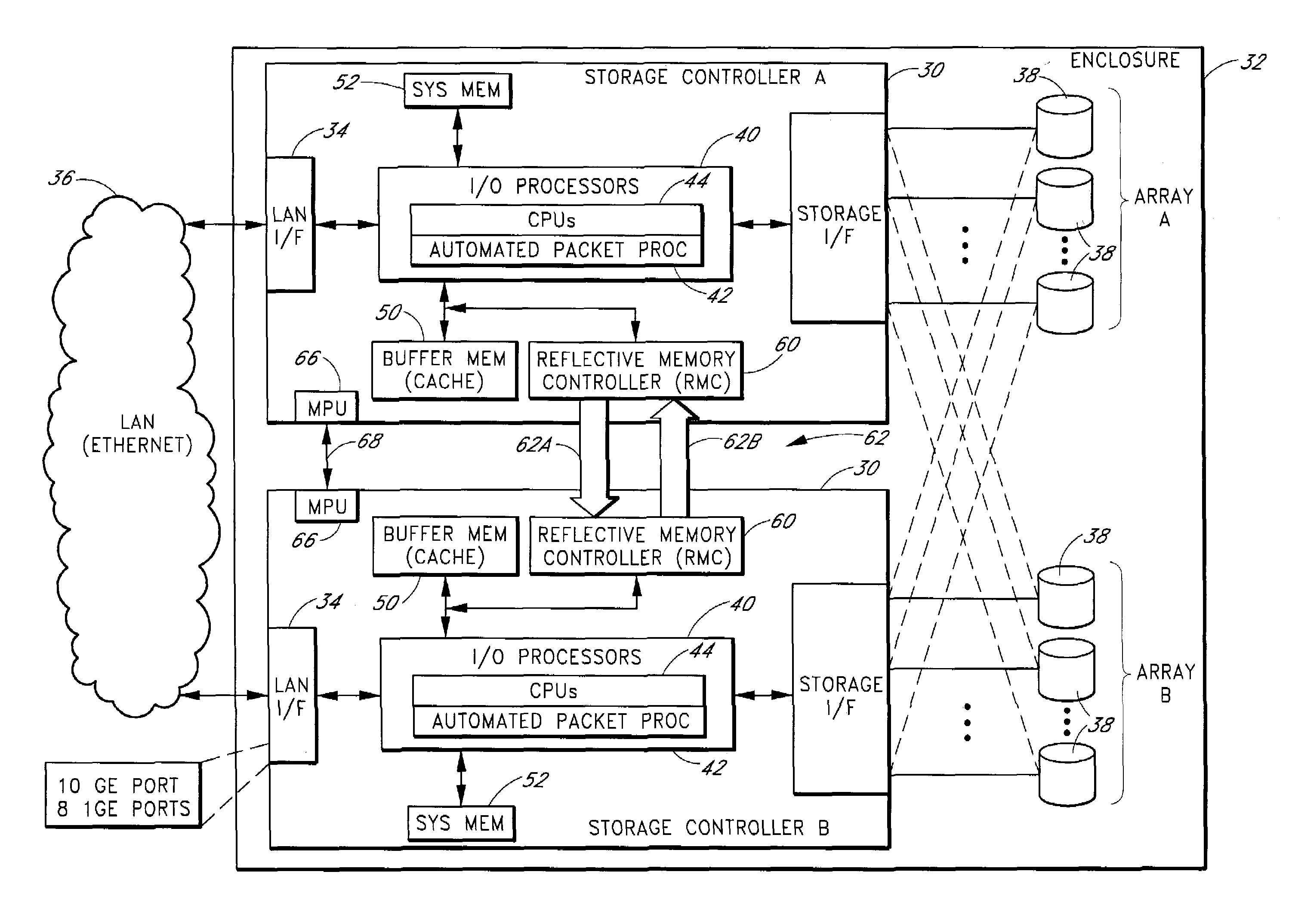
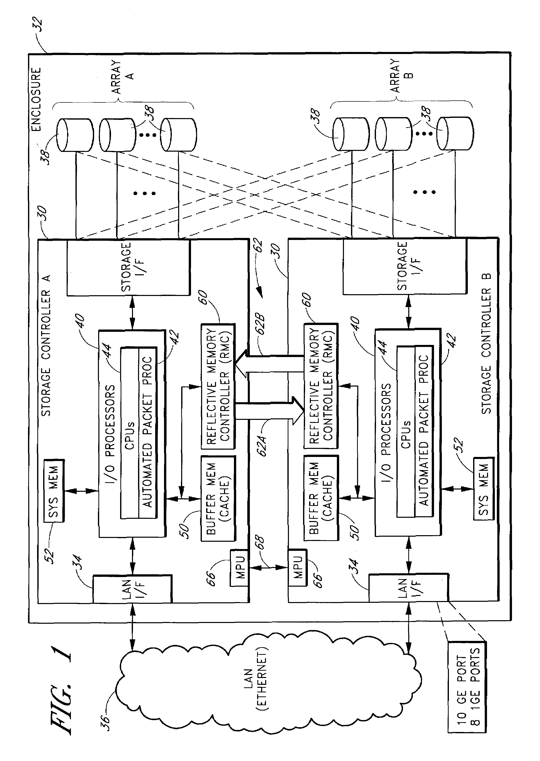
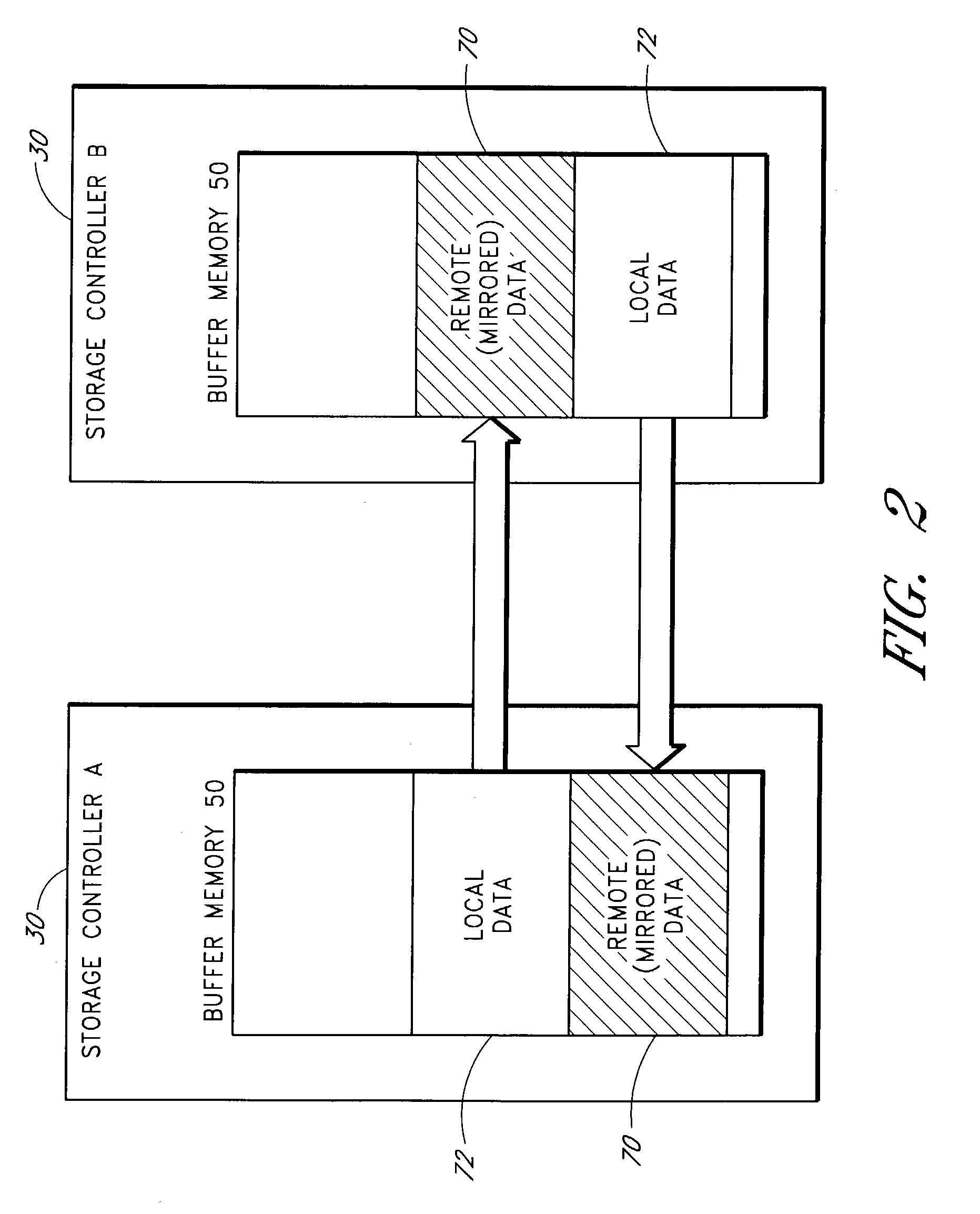
[0023]A storage system that uses a hardware-implemented, bi-directional reflective memory channel to provide storage controller redundancy will now be described in detail. Throughout the description, reference will be made to numerous implementation details, including but not limited to specific data transfer rates, networking and storage standards, network port configurations, packet formats, protocols, and buffer configurations. These implementation details are provided in order to fully illustrate one particular embodiment of the invention, and not to limit the scope of the invention. The invention is defined only by the appended claims.

I. Table of Abbreviations

[0024]The following abbreviations and acronyms will be used throughout the detailed description of the preferred embodiment.[0025]ACK / NAK: Acknowledgement and Negative Acknowledgement, respectively.[0026]BMI: Buffer Memory Interface[0027]CLH—Cache Line Header[0028]CPU—Central Processing Unit[0029]FIFO—First-in-first-out (b...


PUM


Abstract

A bi-directional reflective memory channel between a pair of storage controllers is used to maintain a mirrored copy of each storage controller's native buffer contents within the buffer of the other storage controller. To maintain such mirrored copies, buffer write operations that fall within a reflective memory segment of one storage controller are automatically reflected across this channel to the other storage controller for execution, and vice versa. The write operations are preferably transmitted across the reflective memory channel using a protocol that provides for error checking, acknowledgements, and retransmissions. This protocol is preferably implemented entirely in automated circuitry, so that the mirrored copies are maintained without any CPU intervention during error-free operation. When a failover occurs, the surviving storage controller uses the mirrored copy of the failed storage controller's native buffer contents to assume control over the failed storage controller's disk drives.

Description

FIELD OF THE INVENTION[0001]The present invention relates to network-based storage systems, and more particularly, to techniques for providing storage controller redundancy within a network-based storage system.BACKGROUND OF THE INVENTION[0002]A variety of network-attached and SAN (Storage Area Network) based storage systems exist for allowing data to be stored on an Ethernet or other IP based network. Typically, these systems include one or more storage controllers, each of which controls and provides network-based access to a respective array of disk drives. Each storage controller typically includes a buffer or cache memory that is used to temporarily store data as it is transferred between the network and that controller's disk drives. For example, incoming data packets containing I / O (input / output) write data may be maintained in a buffer of the storage controller until successfully written to the appropriate disk drives.[0003]Some storage systems implement a storage controller...

Claims


Application Information

Patent Timeline
Patent Type & Authority Patents(United States)
IPC IPC(8): G06F11/00G06F13/12G06F13/00H04L1/22H04B1/74G06F3/06G06F11/20H04L12/56
CPCG06F3/0613G06F3/065G06F3/067G06F11/08G06F11/2074G06F11/2079G06F11/2092H04B1/74H04L1/22H04L49/90Y10S707/99953
Inventor THORPE, ROGER T.BRENES, ERASMOO'NEIL, STEPHENSHEN, ALEC
Owner SUPRO STORTEK CO LTD
Why Eureka
Try Eureka